MV750i E, MV730i E, MV700i E, MV700 E, MV690 E
SERVICE MODE · ADJUSTMENT
6
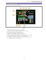
3-4 Indication in Service Mode
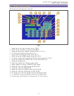
Shown below are the indications in the service mode.
1.
Indicates that the service mode is currently selected. (“SERV”)
2.
MODE : Indicates the MODE currently selected. (RD/WR/ST)
3.
Indicates for which block the command is specified. (MA,MD, CA, CD, etc.)
4.
CS : Indicates the Chip Select currently specified. (0~F)
5.
Function : Indicates the Function currently selected. (00~FF)
6.
ADDR : Indicates the ADDRESS currently selected. (0000~FFFF)
7.
DT : Indicate, in hexadecimal representation, the DATA currently being read or set. (00~FF)
8.
Indicates the mechanical status. (POPUP, STBY, LOAD1, LOAD2, STOP, PLAY)
9.
Indicates the absolute track No.
10. Indicates the mechanical error. (Main power supply backup)
11. Indicates mechanical error history (LITHIUM 3V battery backup)
12. Indicates the version of the MAIN program in the FR MI-COM.
13. Indicates the version of the MODE MI-COM.
14. Indicates the version of the CAMERA program in the FR MI-COM.
15. Indicates the version of the CARD program in the FR MI-COM.
16. E0 : Indicates the error rate of the track that is traced in the CH0 (Low ch) head.
17. E1 : Indicates the error rate of the track that is traced in the CH1 (High ch) head.
18. Data Write status (00: READ mode, 04 : Write preparation, OC : Write execution)
Fig. 7
1
4
2
3
5
6
7
8
9
10
11
12
13
14
15
16
17
18
Summary of Contents for MV750i E
Page 193: ...22 MV750i E MV730i E MV700i E MV700 E MV690 E PARTS LIST Lens Unit Section 1 1 2 3 1 1 1 2 ...
Page 195: ...24 DMC III PARTS LIST 1 10 3 9 5 7 8 6 4 2 3 3 Mechanical Chassis Section 1 ...
Page 197: ...26 DMC III PARTS LIST 1 2 3 4 5 6 7 8 6 1 9 10 13 11 12 Mechanical Chassis Section 2 ...
Page 201: ...30 DMC III PARTS LIST 1 3 4 5 8 9 6 10 7 2 11 Mechanical Chassis Section 4 ...

