MV750i E, MV730i E, MV700i E, MV700 E, MV690 E
SERVICE HINTS
6
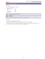
2-2 Camera Picture Faulty
<Hints>
A flow of camera picture (EE) is as below.
CCD
→
CA P.C.B.
→
MAIN P.C.B. (DIGIC DV
→
VIC4)
→
JACK1 / JACK2 P.C.B.
<Check Points>
1)
Check of lens reset (“SERVICE MODE · ADJUSTMENT” P.10)
If no camera picture appears, check if the lens has been reset by means of the service mode. In case of NG, check the lens.
2)
Check of blue back output
If the blue back is confirmed, the signal line subsequent to VIC4 is considered to be OK.
3)
Check of DIGIC DV generation signal (white 100% or color bar) (“SERVICE MODE · ADJUSTMENT” P.9)
The white 100% or color bar signals are generated by the DIGIC DV on the MAIN P.C.B. In the service mode, if the output of the
white 100% or color bar signal is attained, the signal line subsequent to DIGIC DV is considered to be OK.
4)
Check of CCD output
The CCD output is sampled by IC1002 (TG/CDS/AGC/AD). Check the signal.
5)
Check by command particular to camera (“SERVICE MODE · ADJUSTMENT” P.9)
Check the operation of White balance, AGC, IRIS, etc. in the service mode.
Summary of Contents for MV750i E
Page 193: ...22 MV750i E MV730i E MV700i E MV700 E MV690 E PARTS LIST Lens Unit Section 1 1 2 3 1 1 1 2 ...
Page 195: ...24 DMC III PARTS LIST 1 10 3 9 5 7 8 6 4 2 3 3 Mechanical Chassis Section 1 ...
Page 197: ...26 DMC III PARTS LIST 1 2 3 4 5 6 7 8 6 1 9 10 13 11 12 Mechanical Chassis Section 2 ...
Page 201: ...30 DMC III PARTS LIST 1 3 4 5 8 9 6 10 7 2 11 Mechanical Chassis Section 4 ...

