MV750i E, MV730i E, MV700i E, MV700 E, MV690 E
SERVICE MODE · ADJUSTMENT
15
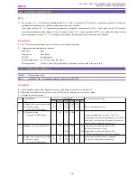
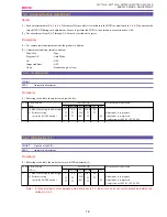
5-2-2 Cam Correction (AUTO)
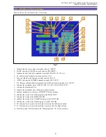
CHART
CZ adjustment chart
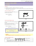
SPEC.
Automatic adjustment
Procedure)
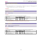
(1) Quit the service mode, and turn power OFF/ON.
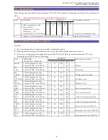
(2) Perform the cam correction by following the table below.
(3) Quit the service mode, turn power off/on, and then check that proper focusing can be attained in normal zooming operation (AF
OFF).
(4) If the result is NG, perform 5-2-1 : CZ automatic adjustment and 5-2-2 : Cam correction (AUTO).
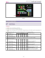
ST EP PROCEDURE
Microcomputer operation
CAM CORRECT ION
CS
Function MD ADDR DT
ST 2
1
1) Make the setting shown at right.
2
08
ST
3101
00
2) Perform storing.
↑
↑
RD
↑
01
(press the PAUSE button.)
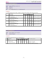
2
3
1) Make the setting shown at right.
2
08
ST
3202
--
↑
↑
WR
↑
↑
2) Perform storing.
↑
↑
RD
↑
02
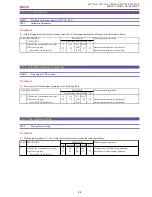
Correction value measurement.
(press the PAUSE button.)
Completion with ST 2:02.
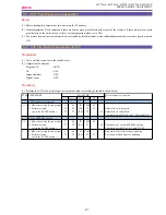
4
1) Make the setting shown at right.
2
08
ST
3104
--
2) Perform storing.
↑
↑
RD
↑
04
Correction value calculation.
(press the PAUSE button.)
Completion with ST 2:04.
5
1) Make the setting shown at right.
2
08
ST
3105
--
2) Perform storing.
↑
↑
RD
↑
AA Completion of correction value writing.
(press the PAUSE button.)
Completion with ST 2:AA.
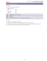
6
1) Make the setting shown at right.
0
08
ST
0081
--
Preparation for flash memory updating.
2) Perform storing.
↑
↑
RD
↑
↑
Execution of flash memory updating.
(press the PAUSE button.)
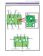
Cancel the service mode, and set t he zoom position to the telephoto end. After focus movement is stopped,
turn OFF the AF function.
MONIT OR
Fig. 12
ST2
MOVIE
Summary of Contents for MV750i E
Page 193: ...22 MV750i E MV730i E MV700i E MV700 E MV690 E PARTS LIST Lens Unit Section 1 1 2 3 1 1 1 2 ...
Page 195: ...24 DMC III PARTS LIST 1 10 3 9 5 7 8 6 4 2 3 3 Mechanical Chassis Section 1 ...
Page 197: ...26 DMC III PARTS LIST 1 2 3 4 5 6 7 8 6 1 9 10 13 11 12 Mechanical Chassis Section 2 ...
Page 201: ...30 DMC III PARTS LIST 1 3 4 5 8 9 6 10 7 2 11 Mechanical Chassis Section 4 ...

