MV750i E, MV730i E, MV700i E, MV700 E, MV690 E
DISASSEMBLING
17
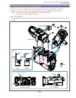
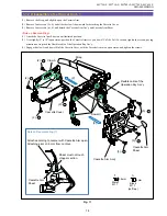
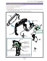
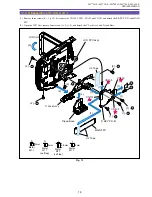
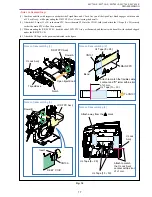
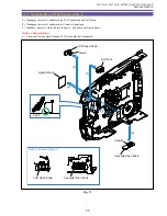
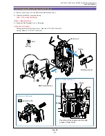
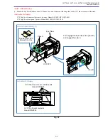
<Notes on Reassembling>
(1) Combine and slide with respect to each other the Tripod Base and C Lock Ass’y until the Open Eject Knob engages with the notch
of C Lock Ass’y, while preventing the D SW FPC Ass’y from leaving the dowel A.
(2) Attach the UL tape (13
×
30) to the main FPC. Insert the main FPC into the CN101, fold it, and attach the UL tape (9
×
25) securely
so that the main FPC will not be unseated.
(3) When mounting the R KEY P.C.B., bend the end of LCD FPC Ass’y as illustrated, and fasten it with dowel B with the bend slipped
under the R KEY P.C.B.
(4) Attach the UL Tape to the positions indicated in the figure.
Fig. 14
Note on Reassembling (1)
Note on Reassembling (2)
Note on Reassembling (3)
Note on Reassembling (4)
MAIN P.C.B.
R-KEY P.C.B.
DH2-5154-000
Dowel A
Notch
Dowel B
Insert
Attach away from the
mark
Attach to match
the C Lock Ass'y
contour within error
of
±
1 mm.
Attach to match the flexible cable
contour and "D" letter within error
of
±
1 mm.
LCD FPC Ass'y
R KEY P.C.B.
C Lock Ass'y
Tripod Base
Open Eject Knob
D SW FPC Ass'y
To CN101
Bend
CN100
UL Tape (9
×
25)
UL Tape (13
×
30)
DH2-5154
C Lock
Ass'y
MAIN FPC
CN101
UL Tape (9
×
25)
UL Tape (13
×
30)
Summary of Contents for MV750i E
Page 193: ...22 MV750i E MV730i E MV700i E MV700 E MV690 E PARTS LIST Lens Unit Section 1 1 2 3 1 1 1 2 ...
Page 195: ...24 DMC III PARTS LIST 1 10 3 9 5 7 8 6 4 2 3 3 Mechanical Chassis Section 1 ...
Page 197: ...26 DMC III PARTS LIST 1 2 3 4 5 6 7 8 6 1 9 10 13 11 12 Mechanical Chassis Section 2 ...
Page 201: ...30 DMC III PARTS LIST 1 3 4 5 8 9 6 10 7 2 11 Mechanical Chassis Section 4 ...

