MV750i E, MV730i E, MV700i E, MV700 E, MV690 E
DISASSEMBLING
21
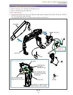
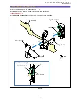
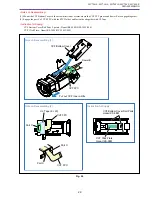
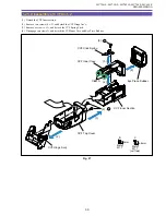
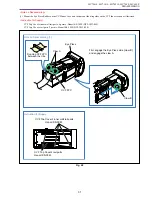
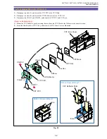
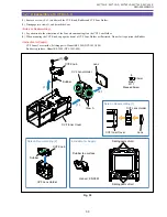
1-18 Disassembly of LCD Unit - 1
Note : The LCD Unit can be disassembled without detaching the Right Cover Unit.
(1) Remove three screws (b
×
3) and four claws A, B, C and D, and detach the LCD Top Cover.
Note : Detach the LCD Top Cover in the order of claws A, B, C and D, paying attention not to damage the claw
receiving sections on the LCD Bottom Cover.
(2) Disconnect the CN901 and CN903, and detach the LCD Hinge Unit and LCD Spring.
(3) Remove the LCD Bottom Cover and LCD Bottom Cover Sheet.
Fig. 18
3mm
Metal
M1.7
b
(1) - b
(1) - b
(1) - b
Claw A
Claw B
Claw C
Claw D
LCD Top Cover
LCD Hinge Unit
CN901
CN903
LCD Bottom Cover
LCD Bottom
Cover Sheet
(1)
(2)
(2)
(3)
(3)
LCD Spring
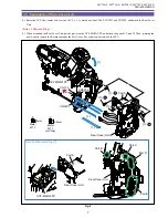
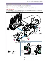
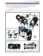
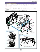
Summary of Contents for MV750i E
Page 193: ...22 MV750i E MV730i E MV700i E MV700 E MV690 E PARTS LIST Lens Unit Section 1 1 2 3 1 1 1 2 ...
Page 195: ...24 DMC III PARTS LIST 1 10 3 9 5 7 8 6 4 2 3 3 Mechanical Chassis Section 1 ...
Page 197: ...26 DMC III PARTS LIST 1 2 3 4 5 6 7 8 6 1 9 10 13 11 12 Mechanical Chassis Section 2 ...
Page 201: ...30 DMC III PARTS LIST 1 3 4 5 8 9 6 10 7 2 11 Mechanical Chassis Section 4 ...

