MV750i E, MV730i E, MV700i E, MV700 E, MV690 E
SERVICE MODE · ADJUSTMENT
9
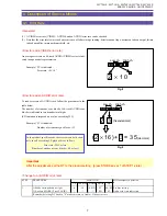
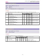
4-3 Cleaning Mode
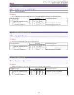
When cleaning the head with hard-type cleaning tape (DY9-1384-000), set up the cleaning mode according to the procedure given
below.
Note :
After head cleaning, be sure to restore the settings to normal.
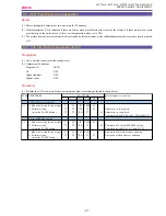
4-4 Commands Particular to Camera
<Outline>
(1) The commands particular to camera are provided for checking the operation.
(2) Make preparation according to the table below and carry out the desired commands particular to camera.
(3) To restore any setting back to the original status, press the PAUSE key (STORE) for each item again in the “ST” mode.
Turning the power OFF/ON resets all the settings.
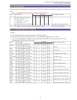
ST EP
PROCEDURE
MONIT OR
Microcomputer operation
CS
Function
ADDR MODE
DT
1
1) Make setting shown at right.
0
10
0111
ST
--
2) Increases DT by 2.
↑
↑
↑
↑
--
(Change bit-02 to 1 from 0.)
(Example: 80
→
82)
3) Perform ST ORE. (Press PAUSE key.
↑
↑
↑
RD
--
Completion of cleaning mode setup
2
1) Change over to the normal mode and turn OFF the power supply.
Resetting of cleaning mode
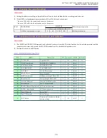
ST EP
PROCEDURE
Microcomputer operation
CAM SPECIAL COMMAND
CS
Function
ADDR MODE
DT
WB SET
1) Make setting shown at right.
2
08
3300
ST
--
2) Execute ST ORE. (Press PAUSE.)
↑
↑
↑
RD
--
WB is set.
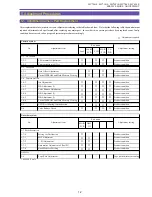
WB
1) Make setting shown at right.
2
08
3301
ST
--
LOCK
2) Execute ST ORE. (Press PAUSE.)
↑
↑
↑
RD
--
WB is locked.
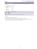
WB
1) Make setting shown at right.
2
08
3302
ST
--
T URBO
2) Execute ST ORE. (Press PAUSE.)
↑
↑
↑
RD
--
WB high-speed setting mode
WB
1) Make setting shown at right.
2
08
3303
ST
--
OUT DOOR 2) Execute ST ORE. (Press PAUSE.)
↑
↑
↑
RD
--
WB outdoor mode
WB
1) Make setting shown at right.
2
08
3304
ST
--
INDOOR
2) Execute ST ORE. (Press PAUSE.)
↑
↑
↑
RD
--
WB indoor mode
IRIS
1) Make setting shown at right.
2
08
3305
ST
--
OPEN
2) Execute ST ORE. (Press PAUSE.)
↑
↑
↑
RD
--
T he iris is opened forcibly.
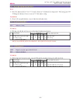
IRIS
1) Make setting shown at right.
2
08
3306
ST
--
CLOSE
2) Execute ST ORE. (Press PAUSE.)
↑
↑
↑
RD
--
T he iris is closed forcibly.
AGC
1) Make setting shown at right.
2
08
3309
ST
--
MAX
2) Execute ST ORE. (Press PAUSE.)
↑
↑
↑
RD
--
A value of AGC gain is maximized.
AGC
1) Make setting shown at right.
2
08
330A
ST
--
MIN
2) Execute ST ORE. (Press PAUSE.)
↑
↑
↑
RD
--
A value of AGC gain is minimized.
COLOR
1) Make setting shown at right.
2
08
330B
ST
--
BAR
2) Execute ST ORE. (Press PAUSE.)
↑
↑
↑
RD
--
Outputs color bar from DIGIC DV.
White
1) Make setting shown at right.
2
08
330C
ST
--
100%
2) Execute ST ORE. (Press PAUSE.)
↑
↑
↑
RD
--
Outputs white 100% from DIGIC DV.
White
1) Make setting shown at right.
2
08
330D
ST
--
50%
2) Execute ST ORE. (Press PAUSE.)
↑
↑
↑
RD
--
Outputs white 50% from DIGIC DV.
MONIT OR
Summary of Contents for MV750i E
Page 193: ...22 MV750i E MV730i E MV700i E MV700 E MV690 E PARTS LIST Lens Unit Section 1 1 2 3 1 1 1 2 ...
Page 195: ...24 DMC III PARTS LIST 1 10 3 9 5 7 8 6 4 2 3 3 Mechanical Chassis Section 1 ...
Page 197: ...26 DMC III PARTS LIST 1 2 3 4 5 6 7 8 6 1 9 10 13 11 12 Mechanical Chassis Section 2 ...
Page 201: ...30 DMC III PARTS LIST 1 3 4 5 8 9 6 10 7 2 11 Mechanical Chassis Section 4 ...

