MV750i E, MV730i E, MV700i E, MV700 E, MV690 E
DISASSEMBLING
8
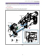
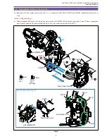
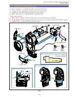
1-6 Separation of Left Cover Unit and JACK 2 P.C.B.
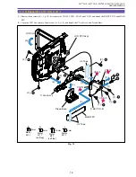
(1) Remove two screws (b
×
2), disconnect the CN2102, and detach the JACK 2 P.C.B.
(2) Disconnect the CN91, and detach the JACK 2-MAIN FPC from the JACK 2 P.C.B.
(3) Remove four screws (b
×
3, c
×
1), disconnect the UL Tape and CN101, and detach the Left Cover Unit.
<Note on Reassembling>
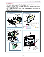
(1) When mounting the Left Cover Unit, tighten four screws (b
×
3, c
×
1) in the illustrated order with the CVF Unit kept raised.
(2) Attach the UL Tape to the position indicated in the figure.
Fig. 5
3mm
Metal
M1.7
Metal
M1.7
(self tap)
4.5mm
b
c
Note on Reassembling (1),(2)
3
CN2102
CN91
(3) - c
(3) - b
(1) - b
(3)
(3)
(1)
(2)
JACK 2-MAIN FPC
Left Cover Unit
JACK 2 P.C.B.
Reference for
attachment
:
±
1mm
Press until
held back
connector.
CN101
(3) - b
UL Tape
1
2
UL Tape(9
×
30)
Summary of Contents for MV750i E
Page 193: ...22 MV750i E MV730i E MV700i E MV700 E MV690 E PARTS LIST Lens Unit Section 1 1 2 3 1 1 1 2 ...
Page 195: ...24 DMC III PARTS LIST 1 10 3 9 5 7 8 6 4 2 3 3 Mechanical Chassis Section 1 ...
Page 197: ...26 DMC III PARTS LIST 1 2 3 4 5 6 7 8 6 1 9 10 13 11 12 Mechanical Chassis Section 2 ...
Page 201: ...30 DMC III PARTS LIST 1 3 4 5 8 9 6 10 7 2 11 Mechanical Chassis Section 4 ...

