MV750i E, MV730i E, MV700i E, MV700 E, MV690 E
SERVICE MODE · ADJUSTMENT
4
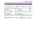
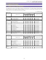
3. Service Modes
3-1 Outline
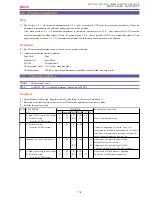
(1) The service mode in this equipment uses the wireless remote controller. (To be used in remote control code 2)
(2) For changeover to the service mode, a dedicated tool (CASSETTE, SERVICE MODE: DY9-1386-000) is required in addition to
the wireless remote controller.
* In case of MV700i E, MV700 E, MV690 E, an extension connector with remote control beam sensor (DY9-1394-000)
is further necessary.
(3) Mode changeover is available between the service mode and the normal mode using the “Audio dubbing” and “SLOW” keys of the
wireless remote controller.
As long as power is ON, the service mode is available even if the “CASSETTE, SERVICE MODE” is removed.
(4) In the service mode, changeover of the main unit operation mode can be handled using the keys on the main unit and the remote control
mode 1.
(5) In the service mode, safety functions such as for mechanical error detection, DEW detection and low voltage detection are canceled.
(6) In the service mode, the LCD mirror function is canceled.
3-2 How to Change Over to Service Mode
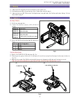
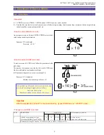
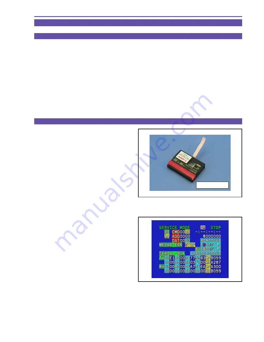
(1) Cassette for changeover to service mode (DY9-1386-000)
Set the in the equipment and load the data.
* In case of MV700i E, MV700 E, MV690 E, also mount
the extension connector with remote control beam
sensor (DY9-1394-000) referring to Fig. 1.
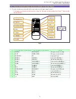
(2) Press the “Dubbing” key on the wireless remote controller
that is set at Remote controller code 2.
* To changeover to Remote controller code 2, press
“Remote controller setting” and “Zoom T” keys si-
multaneously for 2 sec.
* The remote controller code setting on the DVC main
unit is operable both at remote controller codes 1
and 2.
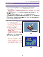
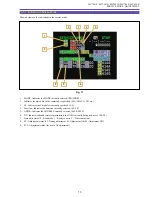
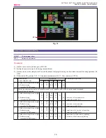
(3) Now the changeover to the service mode has been completed
and the SERVICE MODE appears on the screen.
* Pressing the “SLOW” key performs the changeover
to the normal mode from the service mode.
As long as the power supply is ON, the service mode
is available by setting the “Audio dubbing” key even
if the cassette for transfer to service mode is re-
moved.
Fig. 4
DY9-1386-000
Fig. 5
Summary of Contents for MV750i E
Page 193: ...22 MV750i E MV730i E MV700i E MV700 E MV690 E PARTS LIST Lens Unit Section 1 1 2 3 1 1 1 2 ...
Page 195: ...24 DMC III PARTS LIST 1 10 3 9 5 7 8 6 4 2 3 3 Mechanical Chassis Section 1 ...
Page 197: ...26 DMC III PARTS LIST 1 2 3 4 5 6 7 8 6 1 9 10 13 11 12 Mechanical Chassis Section 2 ...
Page 201: ...30 DMC III PARTS LIST 1 3 4 5 8 9 6 10 7 2 11 Mechanical Chassis Section 4 ...

