
COPYRIGHT © 2001 CANON INC.
2000 2000 2000 2000
CANON iR2200/iR2800/iR3300 REV.0 MAR. 2001
CHAPTER 4 TROUBLESHOOTING IMAGE FAULTS/MALFUNCTIONS
4-29 T
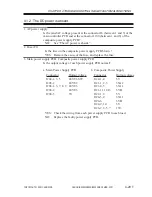
4.1.2 The DC power is absent.
1. AC power supply
Is the rated AC voltage present at the connector J6 (between 1 and 3) of the
main controller PCB and at the connector J100 (between 1 and 3) of the
composite power supply PCB?
NO:
See “The AC power is absent.”
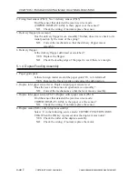
2. Fuse (F1)
Is the fuse on the composite power supply PCB blown ?
YES: Remove the cause of the fuse, and replace the fuse.
3. Main power supply PCB, Composite power supply PCB
Is the output voltage of each power supply PCB normal?
a. Main Power Supply PCB
b. Composite Power Supply
YES: Check the wiring from each power supply PCB to each load.
NO:
Replace the faulty power supply PCB.
Connector
J202-1, 3, 5
J203-2
J204-1, 3, 7, 8, 9
J206-2
J206-3
Output voltage
24VU1-SW
24VU2
24VU3
24VU3
5V
Connector
J120-1, 4
J121-1, 2, 3
J121-4, 5
J121-11,12,13
J122-1, 2
J124-3, 4
J124-6
J124-9, 10
J126-2, 3, 5, 7
Output voltage
5V
3VA2
3VA1
3VB
5V
3VA1
3VB
5V
13V
Summary of Contents for iR2200 Series
Page 8: ......
Page 12: ......
Page 30: ......
Page 32: ......
Page 54: ......
Page 86: ......
Page 90: ......
Page 94: ......
Page 96: ......
Page 124: ......
Page 142: ......
Page 152: ......
Page 160: ......
Page 168: ......
Page 178: ......
Page 180: ......
Page 222: ......
Page 224: ......
Page 278: ......
Page 280: ......
Page 298: ......
Page 300: ......
Page 324: ......
Page 368: ......
Page 386: ......
Page 388: ......
Page 404: ......
Page 414: ......
Page 416: ......
Page 422: ......
Page 424: ......
Page 434: ......
Page 436: ......
Page 440: ......
Page 468: ......
Page 473: ......
Page 550: ......
Page 552: ......
Page 658: ......
Page 704: ......
Page 706: ......
Page 754: ......
Page 756: ......
Page 760: ......


