


COPYRIGHT © 2001 CANON INC.
2000 2000 2000 2000
CANON iR2200/iR2800/iR3300 REV.0 MAR. 2001
CHAPTER 2 MAIN CONTROLLER
2-15 S
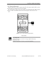
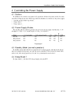
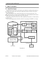
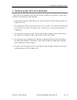
4 Controlling the Power Supply
4.1 Outline
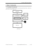
In addition to its control in response to the operation of the main power switch, the main
controller PCB possesses the following control mechanisms in relation to the power supply:
•
Standby mode (normal operation)
•
Sleep mode 1
•
Sleep mode 2
4.2 Power Supply Modes
The machine has the following modes for each of its power supply mechanisms; +3.3V
all-night (3.3 VB), +3.3V non-all night (3.3 VA), +5V, and 24V:
Mode
+3.3V all night
+3.3V non-all night
+5V
+24V
LCD
Standby
Yes
Yes
Yes
Yes
Yes
Sleep mode 1
Yes
Yes
Yes
Yes
No
Sleep mode 2
Yes
No
No
No
No
T02-402-01
4.3 Standby Mode (normal operation)
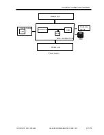
In standby mode, the machine is in operation or is ready operate, and nearly all compo-
nents are supplied with power; not only the main controller PCB, but also the reader unit,
printer unit, and control panel are all ready for communication and control.
4.4 Sleep Mode 1
In sleep mode 1, only the LCD image desplay remains OFF.
Summary of Contents for iR2200 Series
Page 8: ......
Page 12: ......
Page 30: ......
Page 32: ......
Page 54: ......
Page 86: ......
Page 90: ......
Page 94: ......
Page 96: ......
Page 124: ......
Page 142: ......
Page 152: ......
Page 160: ......
Page 168: ......
Page 178: ......
Page 180: ......
Page 222: ......
Page 224: ......
Page 278: ......
Page 280: ......
Page 298: ......
Page 300: ......
Page 324: ......
Page 368: ......
Page 386: ......
Page 388: ......
Page 404: ......
Page 414: ......
Page 416: ......
Page 422: ......
Page 424: ......
Page 434: ......
Page 436: ......
Page 440: ......
Page 468: ......
Page 473: ......
Page 550: ......
Page 552: ......
Page 658: ......
Page 704: ......
Page 706: ......
Page 754: ......
Page 756: ......
Page 760: ......


