


COPYRIGHT © 2001 CANON INC.
2000 2000 2000 2000
CANON iR2200/iR2800/iR3300 REV.0 MAR. 2001
CHAPTER 4 TROUBLESHOOTING IMAGE FAULTS/MALFUNCTIONS
4-49 T
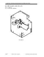
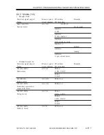
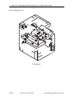
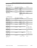
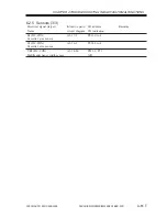
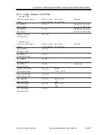
6.2.1 Clutches
•
Reader Unit
The reader unit does not have nay clutch.
•
Printer Unit
Electrical signal (target)
Reference to general
I/O address
Remarks
Name
circuit diagram I/O indication
CL1 (DC-CON)
A3-20-N
P001-5
Vertical path clutch
0: ON, 1: OFF
CL2 (DC-CON)
A3-18-N
P001-6
Multifeeder clutch
0: ON, 1: OFF
CL3 (DC-CON)
A3-20-J
P001-7
Developing clutch
0: ON, 1: OFF
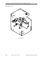
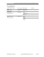
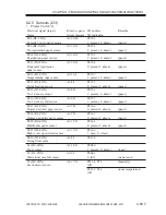
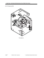
6.2.2 Solenoids, Switches
•
Reader Unit
The reader unit does not have any solenoid or switch.
•
Printer Unit
Electrical signal (target)
Reference to general
I/O address
Remarks
Name
circuit diagram I/O indication
SL1 (DC-CON)
A3-20-N
P002-0
Pickup DOWN solenoid
1: ON, 0: OFF
SL5 (DC-CON)
A3-20-J
P002-3
Multifeeder holding plate
1: ON, 0: OFF
releasing solenoid
SL6 (DC-CON)
A3-20-J
P002-4
Charging roller solenoid
1: ON, 0: OFF
SW1 (MPWS)
A3-12-B
Main power switch
SW2 (MPWS)
A3-12-B
Environment heater switch
SW3 (MPWS)
A3-14-B
P008-7
Front cover switch
0: open, 1: closed
Summary of Contents for iR2200 Series
Page 8: ......
Page 12: ......
Page 30: ......
Page 32: ......
Page 54: ......
Page 86: ......
Page 90: ......
Page 94: ......
Page 96: ......
Page 124: ......
Page 142: ......
Page 152: ......
Page 160: ......
Page 168: ......
Page 178: ......
Page 180: ......
Page 222: ......
Page 224: ......
Page 278: ......
Page 280: ......
Page 298: ......
Page 300: ......
Page 324: ......
Page 368: ......
Page 386: ......
Page 388: ......
Page 404: ......
Page 414: ......
Page 416: ......
Page 422: ......
Page 424: ......
Page 434: ......
Page 436: ......
Page 440: ......
Page 468: ......
Page 473: ......
Page 550: ......
Page 552: ......
Page 658: ......
Page 704: ......
Page 706: ......
Page 754: ......
Page 756: ......
Page 760: ......


