


COPYRIGHT © 2001 CANON INC.
2000 2000 2000 2000
CANON iR2200/iR2800/iR3300 REV.0 MAR. 2001
CHAPTER 6 FIXING SYSTEM
6-17 P
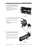
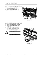
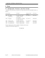
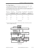
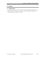
4.1.9 Removing the Fixing Drive Unit
1) Remove the fixing assembly. (p. 6-13P)
2) Check to see that the feeding assembly
is locked in place.
3) Free the claw of the bushing [1], and
slide it to the front.
4) Remove the locking cam unit [2].
F06-401-15
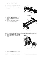
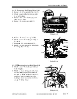
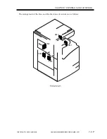
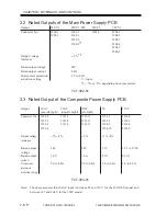
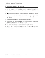
5) Remove the inside cover. (p. 7-14P)
6) Check to see if the feeding assembly is
released.
7) Disconnect the two connectors [1].
8) Remove the four screws [2], and detach
the fixing drive unit [3].
F06-401-16
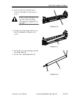
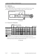
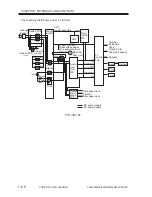
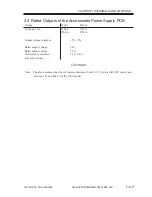
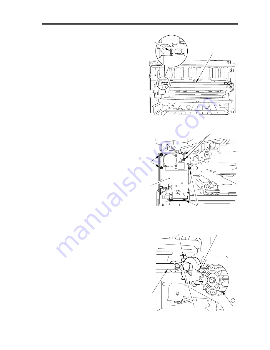
4.1.10 Mounting the Locking Cam Unit
1) Check to see if the feeding assembly is
locked in place.
2) Match the arrow of the gear of the lock-
ing cam unit [1] against the middle of
the gear [3] of the fixing drive unit (e.i.,
where the rear [4] of the gear of the
locking cam unit is in contact with the
cut-up [5] of the frame).
F06-401-17
[1]
[2]
[3]
[2]
[1]
[2]
[4]
[3]
[1]
[5]
[2]
Summary of Contents for iR2200 Series
Page 8: ......
Page 12: ......
Page 30: ......
Page 32: ......
Page 54: ......
Page 86: ......
Page 90: ......
Page 94: ......
Page 96: ......
Page 124: ......
Page 142: ......
Page 152: ......
Page 160: ......
Page 168: ......
Page 178: ......
Page 180: ......
Page 222: ......
Page 224: ......
Page 278: ......
Page 280: ......
Page 298: ......
Page 300: ......
Page 324: ......
Page 368: ......
Page 386: ......
Page 388: ......
Page 404: ......
Page 414: ......
Page 416: ......
Page 422: ......
Page 424: ......
Page 434: ......
Page 436: ......
Page 440: ......
Page 468: ......
Page 473: ......
Page 550: ......
Page 552: ......
Page 658: ......
Page 704: ......
Page 706: ......
Page 754: ......
Page 756: ......
Page 760: ......


