
COPYRIGHT © 2001 CANON INC.
2000 2000 2000 2000
CANON iR2200/iR2800/iR3300 REV.0 MAR. 2001
CHAPTER 4 TROUBLESHOOTING IMAGE FAULTS/MALFUNCTIONS
4-36 T
4.3.2 The scanning lamp fails to go ON.
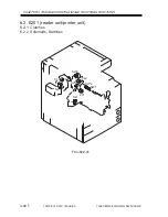
1. Wiring, Connector
Is the connection of the wiring and the connectors between the inverter
PCB (J4061) and the lamp correct?
NO:
Correct the wring, and connect the connectors securely.
2. Inverter PCB
Is ‘E220’ indicated?
YES: Replace the inverter PCB.
3. Scanning lamp, Reader controller PCB
Execute the following in service mode: COPIER>FUNCTION>MISC-
R>SCANLAMP. Is the activation control signal present at J402 of the
reader controller PCB? (J402-2: LMP_ON, J402-3: GND, J402-4: +24 VU)
YES: The scanning lamp is faulty. Replace the lamp.
NO:
The reader controller PCB is faulty. Replace the PCB.
Summary of Contents for iR2200 Series
Page 8: ......
Page 12: ......
Page 30: ......
Page 32: ......
Page 54: ......
Page 86: ......
Page 90: ......
Page 94: ......
Page 96: ......
Page 124: ......
Page 142: ......
Page 152: ......
Page 160: ......
Page 168: ......
Page 178: ......
Page 180: ......
Page 222: ......
Page 224: ......
Page 278: ......
Page 280: ......
Page 298: ......
Page 300: ......
Page 324: ......
Page 368: ......
Page 386: ......
Page 388: ......
Page 404: ......
Page 414: ......
Page 416: ......
Page 422: ......
Page 424: ......
Page 434: ......
Page 436: ......
Page 440: ......
Page 468: ......
Page 473: ......
Page 550: ......
Page 552: ......
Page 658: ......
Page 704: ......
Page 706: ......
Page 754: ......
Page 756: ......
Page 760: ......


