COPYRIGHT © 2001 CANON INC.
2000 2000 2000 2000
CANON iR2200/iR2800/iR3300 REV.0 MAR. 2001
CHAPTER 4 TROUBLESHOOTING IMAGE FAULTS/MALFUNCTIONS
4-63 T
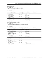
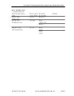
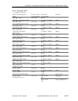
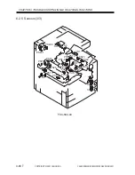
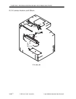
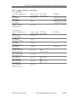
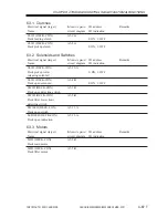
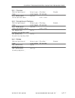
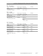
6.2.6 Lamps, Heaters, and Others
•
Reader Unit
Electrical signal (target)
Reference to general
I/O address
Remarks
Name
circuit diagram I/O indication
H4 (MPWS)
A3-9-A
Standard with 100V model
Mirror heater
(accessory for 200V model)
H5 (MPWS)
A3-9-A
Standard with 100V model
Lens heater
(accessory for 200V model)
LAMP1 (R-CON)
A3-17-H
Scanning lanp
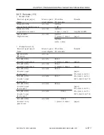
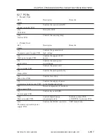
•
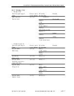
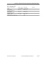
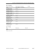
Printer Unit
Electrical signal (target)
Reference to general
I/O address
Remarks
Name
circuit diagram I/O indication
CB1 (MPWS)
A3-14-A
Leakage breaker
H1 (MPWS)
A3-9-C
Fixing main heater
H2 (MPWS)
A3-9-B
Fixing sub heater
H3 (MPWS)
A3-9-B
(accessory)
Cassette heater
LAMP2 (DC-CON)
A3-14-J
P001-1
Pre-exposure lamp
1: ON, 0: OFF
PLG1 (DC-CON)
A3-14-A
Power supply cord
TH1 (MPWS)
A3-12-J
P023-0, P29
Main thermistor
A/D
TH2 (DC-CON)
A3-12-J
P023-1, P30
Sub thermistor
A/D
TP1 (DC-CON)
A3-9-B
Thermal switch
Summary of Contents for iR2200 Series
Page 8: ......
Page 12: ......
Page 30: ......
Page 32: ......
Page 54: ......
Page 86: ......
Page 90: ......
Page 94: ......
Page 96: ......
Page 124: ......
Page 142: ......
Page 152: ......
Page 160: ......
Page 168: ......
Page 178: ......
Page 180: ......
Page 222: ......
Page 224: ......
Page 278: ......
Page 280: ......
Page 298: ......
Page 300: ......
Page 324: ......
Page 368: ......
Page 386: ......
Page 388: ......
Page 404: ......
Page 414: ......
Page 416: ......
Page 422: ......
Page 424: ......
Page 434: ......
Page 436: ......
Page 440: ......
Page 468: ......
Page 473: ......
Page 550: ......
Page 552: ......
Page 658: ......
Page 704: ......
Page 706: ......
Page 754: ......
Page 756: ......
Page 760: ......

