


COPYRIGHT © 2001 CANON INC.
2000 2000 2000 2000
CANON iR2200/iR2800/iR3300 REV.0 MAR. 2001
CHAPTER 6 FIXING SYSTEM
6-4 P
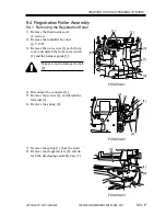
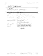
2 Fixing Drive System
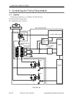
2.1 Outline
The fixing drive system involves the following control mechanisms:
1. Fixing roller drive control
2. Fixing film rotation speed detection/control
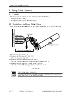
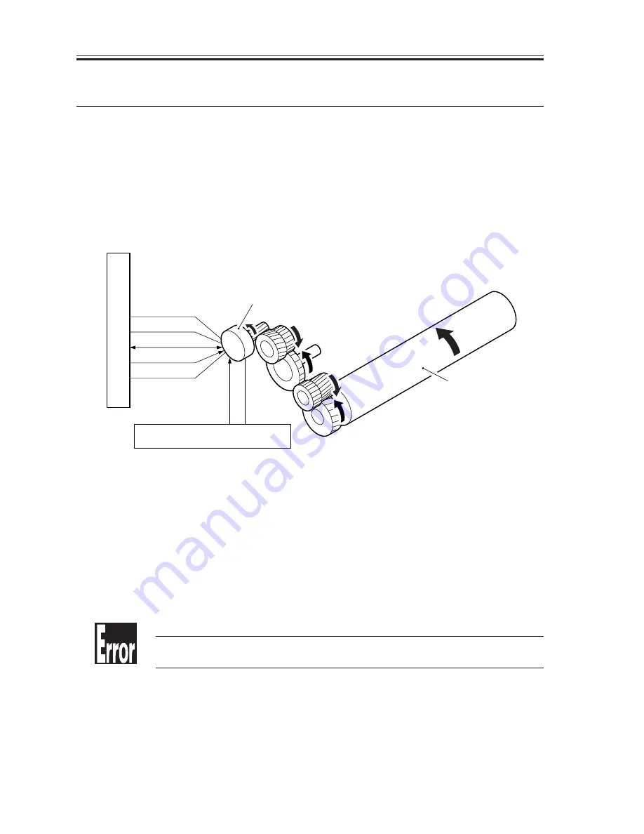
2.2 Controlling the Fixing Roller Drive
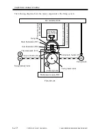
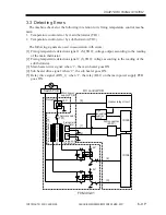
F06-202-01 shows the construction of the control system used for the fixing roller drive:
The following signals are used:
[1] Fixing motor drive signal (FSAR_ON):
when ‘1’, the motor goes ON.
[2] Fixing motor drive lock signal (FSAR_CLK):
when the rotation of the fixing motor reaches a specific speed, ‘0’.
[3] Fixing motor low-speed drive signal (FSAR_SPEED):
when the rotation of the fixing motor is controlled to 1/4, ‘1’.
F06-202-01
E014 (fixing motor speed error)
Indicates that the drive lock signal cannot be detected with 1.3 sec after the
fixing motor drive signal (M4) is generated.
FSAR_ON*
FSAR_LOCK*
N.C
FSRM_CLK
FSRM_SPEED*
M4
24V
GND
DC controller PCB
Fixing motor
Fixing lower roller
Main power supply PCB
Summary of Contents for iR2200 Series
Page 8: ......
Page 12: ......
Page 30: ......
Page 32: ......
Page 54: ......
Page 86: ......
Page 90: ......
Page 94: ......
Page 96: ......
Page 124: ......
Page 142: ......
Page 152: ......
Page 160: ......
Page 168: ......
Page 178: ......
Page 180: ......
Page 222: ......
Page 224: ......
Page 278: ......
Page 280: ......
Page 298: ......
Page 300: ......
Page 324: ......
Page 368: ......
Page 386: ......
Page 388: ......
Page 404: ......
Page 414: ......
Page 416: ......
Page 422: ......
Page 424: ......
Page 434: ......
Page 436: ......
Page 440: ......
Page 468: ......
Page 473: ......
Page 550: ......
Page 552: ......
Page 658: ......
Page 704: ......
Page 706: ......
Page 754: ......
Page 756: ......
Page 760: ......


