


Other Parts
[1]
No.
Parts Name
Main Unit
Reference
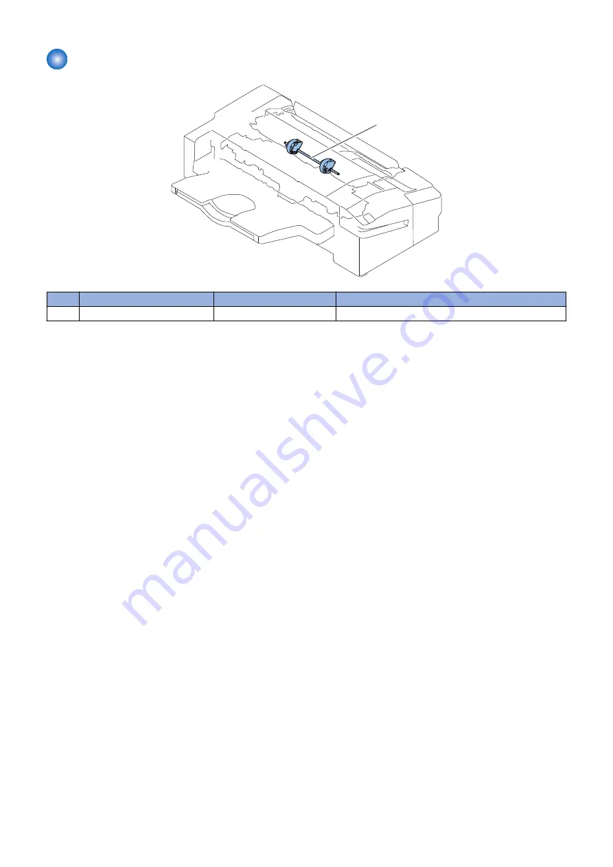
[1]
Return Belt Unit
Product Configuration
“Removing the Return Belt Unit” on page 66
4. Parts Replacement and Cleaning
50
Summary of Contents for Inner Finisher-K1
Page 1: ...Revision 3 0 Inner Finisher K1 Service Manual ...
Page 10: ...Product Overview 1 Features 5 Specifications 6 Name of Parts 9 ...
Page 47: ...Periodical Service 3 Periodic Servicing Tasks 42 ...
Page 94: ...Troubleshooting 6 Making Initial Checks 89 Processing Tray Area 90 ...
Page 109: ...11 1x 12 7 Installation 103 ...
Page 112: ...APPENDICES Service Tools 107 General Circuit Diagram 108 ...


