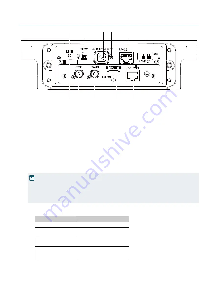
13
Receptacle Unit
(1)
RE
S
ET switch
Reset the camera settings to factory defaults.
For details, refer to "Restoring to the Factory Default Settings" (P. 96).
(2)
DIP
S
W (switch)
These switches are for future expansion.
(3)
DC IN 12V terminal
Input terminal of the DC power supply. Use the included power cable to connect to the power supply.
The black line with white indication line is +, and just the black line is -.
Connect to the power supply that meets the installation site requirements (approved products and the
environment) and product specifications. In addition, note that inrush current may cause the power supply to be
insufficient and cause failure when power is turned on. Therefore, it is recommended to use a power supply with
a power capacity of two to three times the rated capacity or more. For the power supply, refer to "Others"
(4)
POWER lamp
(11) (10)
(9)
(8)
(7)
(6)
(5)
(4)
(3)
(2)
(1)
Important
• Use the included power cable when using the DC power supply or AC adapter.
• The terminal has a block part to prevent incorrect insertion. Ensure the power cable is fully inserted into the terminal, and the
POWER lamp blinks (green).
• The incorrect insertion prevention block part is designed to have a little room for play so that it can move. This is not a defect.
Lamp status
S
tatus
Green light ON
Power ON
Green light BLINKING
Starting/Rebooting
Changing to or from standby
Orange light ON
Standby
Insufficient power
Orange light BLINKING
Pan/Tilt position error
Firmware being updated
Device failure/Error


