DOWNMIXING
When a surround audio feed is routed to a mono or stereo destination, its component legs are combined using predefined
level settings to ensure the resultant mono or stereo feed is accurate and appropriate. This process is referred to as
downmixing.
Downmixing happens automatically whenever a surround feed is routed to a non-surround destination. All internal
downmixing uses LoRo values.
LoRo and LtRt
When configuring a 5.1 main there are two sets of downmix options available: LoRo and LtRt. LoRo is simply the surround
channels summed together as follows:
•
L + Ls+ C = Lo
•
R + Rs + C = Ro
LoRo takes away all front to rear sound separation and leaves a stereo mix which is also compatible with mono systems.
LtRt uses phase processing prior to summing channels together to provide a stereo mix which is compatible with Dolby
Pro Logic systems and can be decoded to recreate the original 5.1 mix. LtRt feeds are not mono-compatible.
Note: When a 5.1 main is set for Lt/Rt, only the downmix audio that is patched out of the Summa system is phase
encoded. All internal routing of the 5.1 main to stereo destinations remains as LoRo.
Downmix Settings
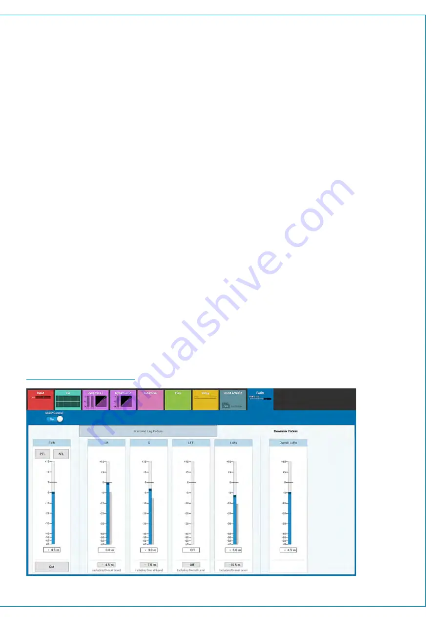
Individual LoRo downmix settings are available for each surround path from the fader control window. Five level
controls are available: Left and right front (LR), centre (C), low frequency effects (LFE), left and right rear (LsRs) and
an overall level control (overall LoRo). Altering the overall LoRo level increases and decreases the overall level of the path.
Individual, path-specific downmix level controls are not available for LtRt, instead the default values set within the Show
settings are used.
FIGURE 1 -
DOWNMIX FADERS
Summary of Contents for SUMMA
Page 11: ...V3 0 196 V3 1 197 V3 1 1 197 V3 2 197 CALREC Putting Sound in the Picture 11...
Page 12: ...12 SUMMA Networked Audio Production System CONTENTS...
Page 13: ...PRODUCT INFORMATION calrec com Putting Sound in the Picture SUMMA...
Page 20: ...20 SUMMA Networked Audio Production System PRODUCT INFORMATION...
Page 21: ...SYSTEM OVERVIEW calrec com Putting Sound in the Picture SUMMA...
Page 33: ...CALREC Putting Sound in the Picture 33...
Page 38: ...38 SUMMA Networked Audio Production System SYSTEM OVERVIEW...
Page 52: ...52 SUMMA Networked Audio Production System SYSTEM OVERVIEW...
Page 53: ...SETTING UP calrec com Putting Sound in the Picture SUMMA...
Page 55: ...FIGURE 1 SYNCHRONISATION OPTIONS CALREC Putting Sound in the Picture 55...
Page 74: ...74 SUMMA Networked Audio Production System SETTING UP...
Page 75: ...GETTING SIGNALS IN AND OUT calrec com Putting Sound in the Picture SUMMA...
Page 93: ...FIGURE 4 SOURCE AND DESTINATION POP UP MEMORY LOAD CALREC Putting Sound in the Picture 93...
Page 105: ...MONITORING calrec com Putting Sound in the Picture SUMMA...
Page 107: ...FIGURE 2 EXAMPLE LOUDSPEAKERS SETUP CALREC Putting Sound in the Picture 107...
Page 110: ...FIGURE 1 THE MONITORING POP UP 110 SUMMA Networked Audio Production System MONITORING...
Page 113: ...METERING calrec com Putting Sound in the Picture SUMMA...
Page 121: ...calrec com Putting Sound in the Picture SUMMA PROCESSING...
Page 153: ...COMMUNICATIONS calrec com Putting Sound in the Picture SUMMA...
Page 161: ...FIGURE 4 MIX MINUS CONTRIBUTION POP UP CALREC Putting Sound in the Picture 161...
Page 163: ...ROUTING calrec com Putting Sound in the Picture SUMMA...
Page 165: ...FIGURE 1 CONFIGURING BUSES AND OUTPUTS CALREC Putting Sound in the Picture 165...
Page 171: ...EXTERNAL INTERFACING calrec com Putting Sound in the Picture SUMMA...
Page 179: ...FIGURE 2 LAN CONFIGURATION WINDOW CALREC Putting Sound in the Picture 179...
Page 180: ...180 SUMMA Networked Audio Production System EXTERNAL INTERFACING...
Page 181: ...CONSOLE FACILITIES calrec com Putting Sound in the Picture SUMMA...
Page 187: ...TERMINOLOGY calrec com Putting Sound in the Picture SUMMA...
Page 195: ...FEATURES BY SOFTWARE VERSION calrec com Putting Sound in the Picture SUMMA...


