Oscillator Controls
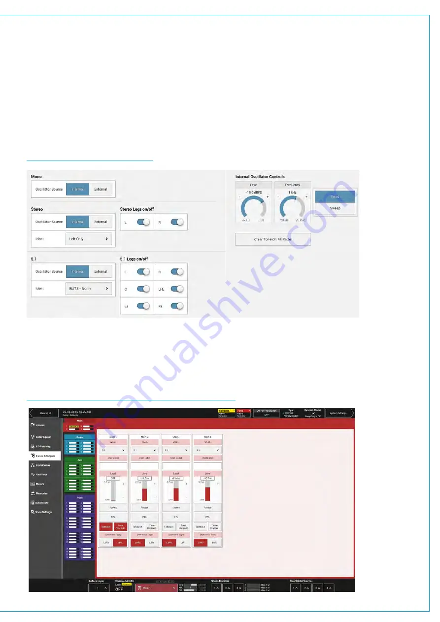
Internal tone signals are generated by Summa’s oscillator which can be controlled from the oscillator setup area.
To access this, tap
OSCILLATOR
in the Show menu.
Summa has one internal oscillator which is controlled using the two rotary controls towards the bottom of the window:
level and frequency. You can set the oscillator to generate a fixed tone at the specified frequency, or a stepped 20 Hz
to 20 kHz tone sweep.
Different tone sources can be set for each path width (mono, stereo and 5.1) using the internal and external tone
source buttons. Selecting
INTERNAL
uses Summa’s internal oscillator as the tone source for that path width, whereas
selecting
EXTERNAL
uses the feed that is currently patched to Summa’s external tone input. Each leg of a stereo or
5.1 tone source can be muted individually.
FIGURE 5 -
OSCILLATOR CONTROLS
Clearing Tone
Tap
CLEAR TONE
at the bottom of the
OSCILLATOR
window to quickly switch off all tone on all paths.
Tone and Talkback Active Notification
Notifications appear in the main header when any tone or talkback is active.
The notifications can be tapped to clear all tone or talkback. See Figure 6 below.
FIGURE 6 - TONE AND TALKBACK ACTIVE NOTIFICATIONS
Summary of Contents for SUMMA
Page 11: ...V3 0 196 V3 1 197 V3 1 1 197 V3 2 197 CALREC Putting Sound in the Picture 11...
Page 12: ...12 SUMMA Networked Audio Production System CONTENTS...
Page 13: ...PRODUCT INFORMATION calrec com Putting Sound in the Picture SUMMA...
Page 20: ...20 SUMMA Networked Audio Production System PRODUCT INFORMATION...
Page 21: ...SYSTEM OVERVIEW calrec com Putting Sound in the Picture SUMMA...
Page 33: ...CALREC Putting Sound in the Picture 33...
Page 38: ...38 SUMMA Networked Audio Production System SYSTEM OVERVIEW...
Page 52: ...52 SUMMA Networked Audio Production System SYSTEM OVERVIEW...
Page 53: ...SETTING UP calrec com Putting Sound in the Picture SUMMA...
Page 55: ...FIGURE 1 SYNCHRONISATION OPTIONS CALREC Putting Sound in the Picture 55...
Page 74: ...74 SUMMA Networked Audio Production System SETTING UP...
Page 75: ...GETTING SIGNALS IN AND OUT calrec com Putting Sound in the Picture SUMMA...
Page 93: ...FIGURE 4 SOURCE AND DESTINATION POP UP MEMORY LOAD CALREC Putting Sound in the Picture 93...
Page 105: ...MONITORING calrec com Putting Sound in the Picture SUMMA...
Page 107: ...FIGURE 2 EXAMPLE LOUDSPEAKERS SETUP CALREC Putting Sound in the Picture 107...
Page 110: ...FIGURE 1 THE MONITORING POP UP 110 SUMMA Networked Audio Production System MONITORING...
Page 113: ...METERING calrec com Putting Sound in the Picture SUMMA...
Page 121: ...calrec com Putting Sound in the Picture SUMMA PROCESSING...
Page 153: ...COMMUNICATIONS calrec com Putting Sound in the Picture SUMMA...
Page 161: ...FIGURE 4 MIX MINUS CONTRIBUTION POP UP CALREC Putting Sound in the Picture 161...
Page 163: ...ROUTING calrec com Putting Sound in the Picture SUMMA...
Page 165: ...FIGURE 1 CONFIGURING BUSES AND OUTPUTS CALREC Putting Sound in the Picture 165...
Page 171: ...EXTERNAL INTERFACING calrec com Putting Sound in the Picture SUMMA...
Page 179: ...FIGURE 2 LAN CONFIGURATION WINDOW CALREC Putting Sound in the Picture 179...
Page 180: ...180 SUMMA Networked Audio Production System EXTERNAL INTERFACING...
Page 181: ...CONSOLE FACILITIES calrec com Putting Sound in the Picture SUMMA...
Page 187: ...TERMINOLOGY calrec com Putting Sound in the Picture SUMMA...
Page 195: ...FEATURES BY SOFTWARE VERSION calrec com Putting Sound in the Picture SUMMA...


