DYNAMICS
Every channel, main, group, aux and track has two dynamics processing modules available to it: Dynamics 1
includes a compressor/limiter and an expander/gate which act in parallel and can be used simultaneously,
Dynamics 2 is a compressor/limiter. Dynamics 1 and 2 modules act in series on the associated path.
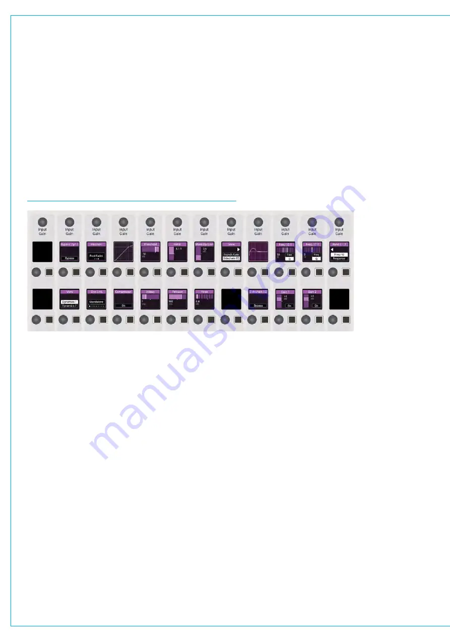
Dynamics controls can be accessed from either the touch display or the surface control cells:
•
With the touch display in ‘active Show’ view, tap the Dynamics 1 or Dynamics 2 processing tabs to access the
relevant module controls.
•
From the surface, push the
ACCESS
control mode button to populate the control cells with dynamics and EQ
controls for the currently accessed path. On a Summa 12+8 surface the control cells on the far left allow you to
switch between viewing dynamics and EQ controls. On the two larger surfaces, both sets of controls are always
displayed. The dynamics controls are shown here:
FIGURE 1 -
CONTROL CELLS—ACCESS MODE—DYNAMICS
Dynamics Modules
Dynamics 1 includes a compressor/limiter module and an expander/gate module, both of which can be switched on and
off individually by tapping the
ON/OFF
toggle switches. The Dynamics 2 module is a compressor/limiter.
Summary of Contents for SUMMA
Page 11: ...V3 0 196 V3 1 197 V3 1 1 197 V3 2 197 CALREC Putting Sound in the Picture 11...
Page 12: ...12 SUMMA Networked Audio Production System CONTENTS...
Page 13: ...PRODUCT INFORMATION calrec com Putting Sound in the Picture SUMMA...
Page 20: ...20 SUMMA Networked Audio Production System PRODUCT INFORMATION...
Page 21: ...SYSTEM OVERVIEW calrec com Putting Sound in the Picture SUMMA...
Page 33: ...CALREC Putting Sound in the Picture 33...
Page 38: ...38 SUMMA Networked Audio Production System SYSTEM OVERVIEW...
Page 52: ...52 SUMMA Networked Audio Production System SYSTEM OVERVIEW...
Page 53: ...SETTING UP calrec com Putting Sound in the Picture SUMMA...
Page 55: ...FIGURE 1 SYNCHRONISATION OPTIONS CALREC Putting Sound in the Picture 55...
Page 74: ...74 SUMMA Networked Audio Production System SETTING UP...
Page 75: ...GETTING SIGNALS IN AND OUT calrec com Putting Sound in the Picture SUMMA...
Page 93: ...FIGURE 4 SOURCE AND DESTINATION POP UP MEMORY LOAD CALREC Putting Sound in the Picture 93...
Page 105: ...MONITORING calrec com Putting Sound in the Picture SUMMA...
Page 107: ...FIGURE 2 EXAMPLE LOUDSPEAKERS SETUP CALREC Putting Sound in the Picture 107...
Page 110: ...FIGURE 1 THE MONITORING POP UP 110 SUMMA Networked Audio Production System MONITORING...
Page 113: ...METERING calrec com Putting Sound in the Picture SUMMA...
Page 121: ...calrec com Putting Sound in the Picture SUMMA PROCESSING...
Page 153: ...COMMUNICATIONS calrec com Putting Sound in the Picture SUMMA...
Page 161: ...FIGURE 4 MIX MINUS CONTRIBUTION POP UP CALREC Putting Sound in the Picture 161...
Page 163: ...ROUTING calrec com Putting Sound in the Picture SUMMA...
Page 165: ...FIGURE 1 CONFIGURING BUSES AND OUTPUTS CALREC Putting Sound in the Picture 165...
Page 171: ...EXTERNAL INTERFACING calrec com Putting Sound in the Picture SUMMA...
Page 179: ...FIGURE 2 LAN CONFIGURATION WINDOW CALREC Putting Sound in the Picture 179...
Page 180: ...180 SUMMA Networked Audio Production System EXTERNAL INTERFACING...
Page 181: ...CONSOLE FACILITIES calrec com Putting Sound in the Picture SUMMA...
Page 187: ...TERMINOLOGY calrec com Putting Sound in the Picture SUMMA...
Page 195: ...FEATURES BY SOFTWARE VERSION calrec com Putting Sound in the Picture SUMMA...


