INSERTS
Inserts provide a quick way to insert signal processing equipment into the system. Faders, groups, mains and the
console monitor output all have an insert.
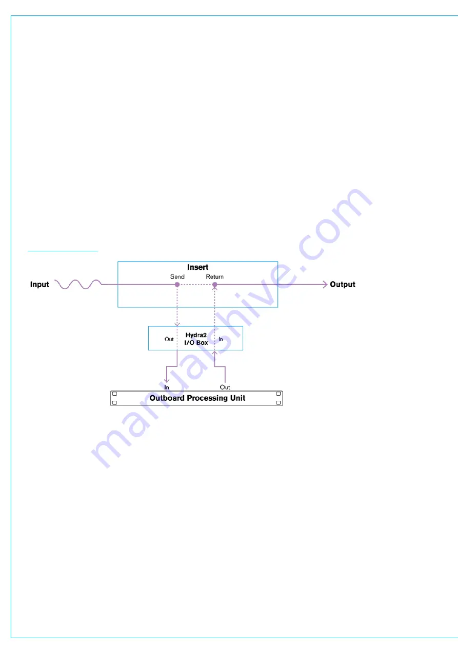
Each insert has a send and a return, providing a convenient break in the signal chain. Sends and returns all appear in the
I/O patching screen where they can be patched to I/O box ports for connection to external devices.
Fader Inserts
Fader inserts are associated to the attached path. If, for example, a channel is attached to fader three and fader three’s
insert is patched to an I/O box, if channel three is moved to a different fader, fader 10 for example, the insert patching will
move along with it to fader 10’s insert send and return.
Patching Inserts
From the Summa surface, insert sends should be connected to outboard inputs and Insert returns should be
connected to outboard outputs. Outboard devices should have their inputs connected to I/O box output ports and their
outputs connected to I/O box input ports, as shown below.
FIGURE 1 -
INSERT
In/Out
Each insert has its own activation in/out button which, for faders, groups and mains can be found in the insert & width
processing tab. The console monitor insert in/out button is accessible from the settings tab within the console monitor
pop-up.
In/out buttons are useful for quickly comparing processed and unprocessed signals.
Summary of Contents for SUMMA
Page 11: ...V3 0 196 V3 1 197 V3 1 1 197 V3 2 197 CALREC Putting Sound in the Picture 11...
Page 12: ...12 SUMMA Networked Audio Production System CONTENTS...
Page 13: ...PRODUCT INFORMATION calrec com Putting Sound in the Picture SUMMA...
Page 20: ...20 SUMMA Networked Audio Production System PRODUCT INFORMATION...
Page 21: ...SYSTEM OVERVIEW calrec com Putting Sound in the Picture SUMMA...
Page 33: ...CALREC Putting Sound in the Picture 33...
Page 38: ...38 SUMMA Networked Audio Production System SYSTEM OVERVIEW...
Page 52: ...52 SUMMA Networked Audio Production System SYSTEM OVERVIEW...
Page 53: ...SETTING UP calrec com Putting Sound in the Picture SUMMA...
Page 55: ...FIGURE 1 SYNCHRONISATION OPTIONS CALREC Putting Sound in the Picture 55...
Page 74: ...74 SUMMA Networked Audio Production System SETTING UP...
Page 75: ...GETTING SIGNALS IN AND OUT calrec com Putting Sound in the Picture SUMMA...
Page 93: ...FIGURE 4 SOURCE AND DESTINATION POP UP MEMORY LOAD CALREC Putting Sound in the Picture 93...
Page 105: ...MONITORING calrec com Putting Sound in the Picture SUMMA...
Page 107: ...FIGURE 2 EXAMPLE LOUDSPEAKERS SETUP CALREC Putting Sound in the Picture 107...
Page 110: ...FIGURE 1 THE MONITORING POP UP 110 SUMMA Networked Audio Production System MONITORING...
Page 113: ...METERING calrec com Putting Sound in the Picture SUMMA...
Page 121: ...calrec com Putting Sound in the Picture SUMMA PROCESSING...
Page 153: ...COMMUNICATIONS calrec com Putting Sound in the Picture SUMMA...
Page 161: ...FIGURE 4 MIX MINUS CONTRIBUTION POP UP CALREC Putting Sound in the Picture 161...
Page 163: ...ROUTING calrec com Putting Sound in the Picture SUMMA...
Page 165: ...FIGURE 1 CONFIGURING BUSES AND OUTPUTS CALREC Putting Sound in the Picture 165...
Page 171: ...EXTERNAL INTERFACING calrec com Putting Sound in the Picture SUMMA...
Page 179: ...FIGURE 2 LAN CONFIGURATION WINDOW CALREC Putting Sound in the Picture 179...
Page 180: ...180 SUMMA Networked Audio Production System EXTERNAL INTERFACING...
Page 181: ...CONSOLE FACILITIES calrec com Putting Sound in the Picture SUMMA...
Page 187: ...TERMINOLOGY calrec com Putting Sound in the Picture SUMMA...
Page 195: ...FEATURES BY SOFTWARE VERSION calrec com Putting Sound in the Picture SUMMA...


