


170
of 216
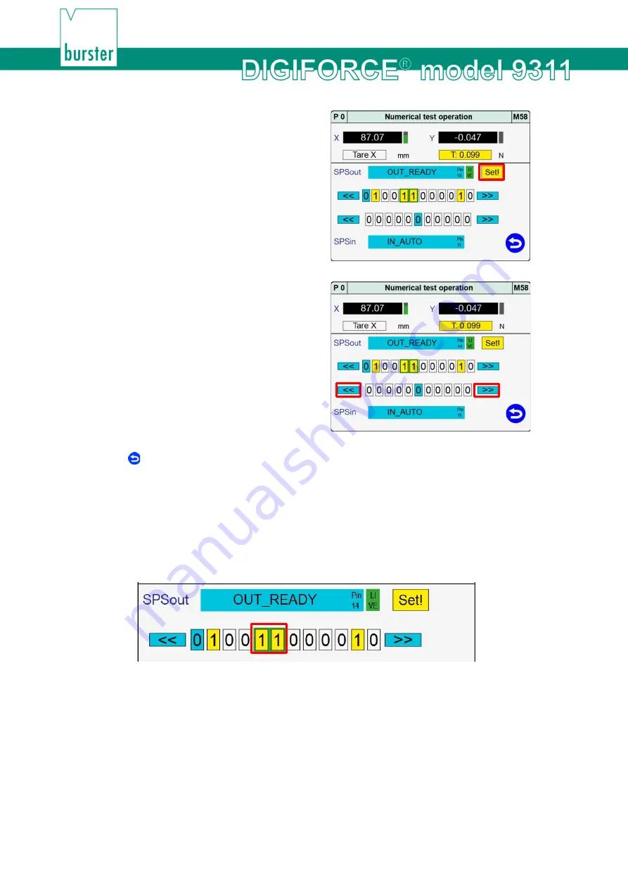
6
Tap
[Set!]
or
[Reset!]
to change the state of
the PLC output.
7
Tap
[<<]
or
[>>]
to select the PLC input you
require.
8
Tap to return to the "Program Setup" menu.
Online switching points
If a measurement exceeds the set limit level then the associated online switching point (S1 to S6)
responds in the "Numerical test operation" menu (M58), provided the signal is highlighted with a green
background (note that with the default configuration only signals S1 and S2 are available). You can
remove the green highlighting by tapping the row containing the PLC outputs. You can then set/reset the
signals manually (for details of how to configure the online switching signals, please see section 6.3.4
"Online switching points" on page 132).
Diagram 75: Numerical Test Operation - Online switching points
You can monitor the behaviour of the switching signals S1 to S6 in this menu (for further details, please
see section 6.3.4 "Online switching points" on page 132). The signals must be highlighted with the "Live"
green background, however, to monitor the live states.
Exception
: an online switching point for measurement channel X with trigger reference is enabled solely
during a measurement in measurement mode or in the "Graphical test operation" menu (M59).
You can assign switching signals S3 to S6 to any PLC output eligible for custom signal assignments
(please see section 6.1.2 "PLC outputs" on page 46).
Summary of Contents for DIGIFORCE 9311
Page 3: ...3of 216...