


30
PANEL PRO
If you look at the draw menu, you will see the drawing entities that EasyCAD will draw.
AvCAM will recognized line, arc, circle, polyline, and point entities.
Draw instruments:
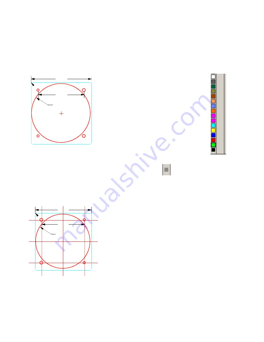
Consider the instrument to the left as a
manufacturer may draw it. This is a standard
cutout for a 3.125” instrument with allowance
for paint.
When EasyCAD opens a new file, the current
layer is “standard”. It is useful to organize
information on layers that can be turned on or
off so as not to clutter other information. Many
of the drawings included in the drawing
package have their roots back in the “DOS”
days when layers were numbered and not
named. Back then we adopted layer 2 as the layer to contain the final
desired cutout sized entities and have not changed it.
We will start by drawing the cutout. Select the layer icon
(right side, icon with 4
horizontal solid lines). Click new and type in “2” for the new layer name. Click new
again and repeat with “1”. On the lines with the layer names there are 3 boxes. The
first box if checked indicates the current layer on which any new entities will reside.
Next to that is a box that if checked indicates that layer is hidden.
For now check the layer 2 box to select it as current, and click ok.
Next move the mouse pointer to the color bar and select
the third color from the bottom “red”.
Click draw>circles>diameter and center. There are a
number of methods to define the entities. In this case we
will enter the diameter of the circle and its center
coordinates. Note the data entry / command bar on the
lower left of the screen. It should say diameter (2.000) or
some other number. The number displayed is the
diameter that will be drawn when you right click or hit enter
unless otherwise specified. In this case type the number
3.140 and hit enter. A 3.140 diameter circle will attach to the mouse pointer. We want a
precise center coordinate, so type the number 0,0 and hit enter or right click on the
mouse.
Ø3.140
2.474
3.250
R0.100
Ø3.140
2.474
3.250
R0.100


