6
Installing the boiler
Logano plus GB312 – 6 720 806 273 (2013/01)
17
Observe the following points when installing the flue ducting:
• The cross-sectional area of the vent pipe must be calculated
according to the applicable regulations. Guidance on the
dimensioning of the flue/air supply system can also be obtained in
the Application Manual GB312 US/CA.
• Select the shortest possible route for the flue pipe.
• Install vent pipes with an upward slope from the boiler (¼ " per foot).
• The application of external insulation on plastic pipes is prohibited.
We recommend installing a safety mesh (bird screen) at the discharge
opening from the vent pipe.
For details of correct dimensioning, contact the venting manufacturer
concerned.
Flue system for multi-boiler systems (cascading systems)
These instructions relate only to single-boiler systems. Flue/air supply
systems for multi-boiler systems must be designed by qualified heating
professionals and approved and guaranteed by the flue system
manufacturer. The venting system must prevent back-flow of flue gas
through boilers that are not in operation.
6.1
Attaching the flue connector to the boiler
Install the selected flue system manufacturer's appropriate flue pipe
adaptor for the boiler according to the manufacturer's instructions.
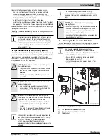
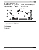
Fig. 11 Connecting the flue connector
[1]
Flue pipe adaptor (available separately)
[2]
Flue pipe adaptor (available separately)
[3]
Fitted gasket
All instructions relating to all parts of the flue gas routing
system, and especially the instructions of the venting
system manufacturer, must be followed. Use only piping
with the appropriate diameter for the output rating of the
boiler and made by the recommended manufacturers
listed in Table 7, 8 or 9.
DANGER:
Risk of fatal injury from escaping flue gases in
the installation room.
▶ The gasket in the flue connector of the condensate
pan must be present, in good order and correctly
inserted.
▶ Installing an air inlet flap in the flue system is not
permitted.
CAUTION:
Risk of system damage due to inadequate
condensate drainage.
▶ Use a suitable siphon to drain condensate that
accumulates in the flue before it reaches the boiler
(maximum distance from boiler: 6 ft).
CAUTION:
Disruption of operation due to high wind.
If no T-piece or 90° elbow is fitted on the end of flue pipe,
high winds may cause the boiler to shut down.
▶ Always make sure that there is a T-piece or a 90°
elbow fitted depending on the design of the flue
system.
▶ Use only a T-piece or 90° elbow (Category IV) made
by the selected flue system manufacturer.
With regard to possible restrictions and inspections for
flue systems, consult the local building and fire safety
authorities. Observe the national regulations.
In the Commonwealth of Massachusetts the
requirements about carbon monoxide detectors must be
followed.
In the case of venting systems sealed with high-
temperature silicone from a cartridge, the silicone must
be allowed to dry for 24 hours before commissioning the
boiler.
DANGER:
Risk of fatal injury due to poisoning by
escaping flue gas.
▶ After carrying out any of the installations referred to,
check that all connections throughout the entire
venting system are properly joined and sealed.
▶ Check seams and joints for leaks.
▶ Have the entire flue system checked once a year by a
qualified heating contractor.
Use a suitable siphon to drain condensate that
accumulates in the flue before it reaches the boiler
(maximum distance to boiler: 6 ft). Condensate must not
be allowed to flow into the appliance.
▶ Ensure that the condensate drain is adequately
dimensioned (at least ¾ ").
▶ Install the vent pipe with an upward slope (¼ " per
foot).
7 747 010 720-11.
3
T
2
3
1


