4
Installing the boiler
Logano plus GB312 – 6 720 806 273 (2013/01)
14
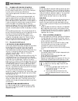
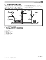
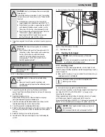
Fig. 7
Transporting the boiler using pipes
[1]
Positions for securing the boiler against slipping
[2]
Pipe (for carrying)
3.2
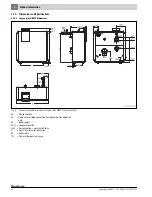
Transporting the boiler on rollers
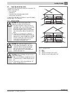
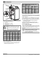
If the route to the installation site is flat, the boiler can also be rolled. This
requires at least 5 lengths of pipe approx. 28 inches long (diameter
1¼ ") to be placed underneath to act as rollers.
▶ Lay the lengths of pipe on the floor spaced about 16 inches apart.
▶ Lift the boiler onto the lengths of pipe and carefully transport it to the
installation site.
Fig. 8
Transporting the boiler on rollers (dimensions in inches)
4
Installing the boiler
This chapter details how to install and site the boiler correctly in the
installation room.
4.1
Installation room requirements
4.2
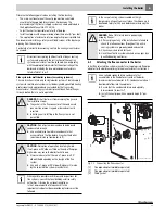
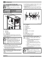
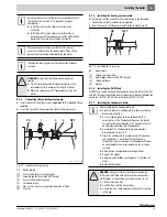
Recommended wall clearances
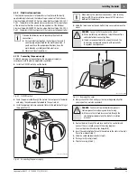
When determining the installation location, take the clearances for the
flue gas routing and the connection pipes into consideration (
Fig. 9,
page 15 and Section 6, page 16, venting system connection and the
piping on the water and gas sides).
You can also use standard transport rollers.
▶ So that the bottom plate is not pressed in, it is
essential to ensure that the weight is evenly
distributed across the load-bearing parts.
7 747 010 720-07.1RS
7 747 010 720-08.1RS
WARNING:
Risk of system damage due to freezing!
▶ Install the heating system in a frost-free room.
DANGER:
Dangers posed by explosive and easily
combustible materials.
▶ Never use or store easily flammable materials (paper,
curtains, clothing, thinners, paints etc.) near the
boiler.
▶ Maintain a clearance of 16 inches from the boiler.
WARNING:
Risk of boiler damage through contaminated
combustion air.
▶ Do not use cleaning agents that contain chlorine or
halogenated hydrocarbons (e.g. in spray cans,
solvents and cleaning agents, paints, glues).
▶ Never use or store chlorinated cleaning agents or
halogenated hydrocarbons in the installation room.
▶ Avoid excessive dust accumulation (building dust) on
or near the boiler.
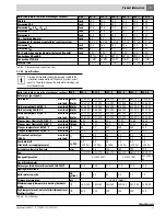
Dimension
Wall clearance (inch)
Minimum
Recommended
A
20
28
B
1)
1) This clearance depends on the venting system installed
22
28
C
20
28
D
20
28
E
1)
6
14
Table 6 Recommended and minimum wall clearances (dimensions in
inches). Minimum clearance dimension E must absolutely be
adhered to.
Allow extra wall clearances for additional components,
for example, indirect water storage tanks, pipe
connections or other components on the flue gas side
etc.


