6
Installing the boiler
Logano plus GB312 – 6 720 806 273 (2013/01)
20
6.6
Installing the wall penetration for the air pipe
To prevent possible recirculation of flue gas, the flue system installer
must take account of effects such as the prevailing wind conditions, e. g.
any eddy zones, the specifics of the site, etc. in the design of the flue and
air supply systems. Buderus can not be held responsible for such
potentially deleterious effects on boiler operation. Multi-boiler systems
must be installed according to the specifications of ANSI Z223.1.
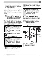
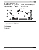
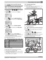
The clearances detailed or illustrated in Fig. 12 and Fig. 16 should be
seen as the absolute minimum and may in some circumstances not be
adequate for specific installations.
Fig. 16 Design of air pipe wall penetration
A
Minimum vertical distance from air intake of another
appliance = 3 ft.; with directly vented appliances, the flue outlet
can be positioned level with the appliance's own air intake
(observe minimum horizontal separation of 4 ft).
[1]
Flue outlet boiler 1
[2]
Inner wall centering and retaining plate
[3]
Boiler sealer
[4]
Outer wall retaining plate
[5]
T-piece or
[6]
90° elbow
[7]
Air intake boiler 1
[8]
Flue outlet boiler 2
[9]
Air intake boiler 2
2
1
4
3
5
7
6
8
9
4 ft min.
10 ft min. (ANSI Z223.1)
4 ft min.
12 in min.
12 in min.
6 720 647 031-01.1T
3 ft min.
A

