9
Heating system inspection
Logano plus GB312 – 6 720 806 273 (2013/01)
48
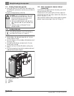
Fig. 67 Testing apparatus set-up for gas valve leak testing
A
Main shutoff valve on inlet-side gas valve
B
Solenoid valve 1
C
Solenoid valve 2
D
Gas shutoff valve on outlet-side gas valve
E
Manual shutoff valve (testing apparatus)
F
Manual shutoff valve (testing apparatus)
G
Hand pump (testing apparatus)
H
Pressure tester (testing apparatus)
I
Low pressure switch (available separately)
1, 2, 3, 4, P Pressure testing points
9.8
Checking for leaks during normal operation
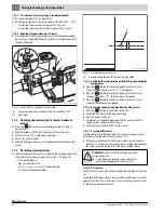
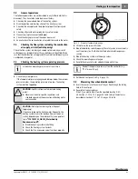
▶ Start up the boiler and check the flange for leaks at maximum output.
▶ Use a leak detecting agent to check all around the flange for leaks.
▶ For details of other leakage checks, refer to Section 7.17, page 38.
9.9
Check ionization current
To ensure trouble-free operation, the ionization current at medium and
maximum output (when flame is lit) should be at least 3 μA.
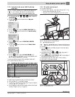
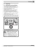
The (flame) ionization current can be read off on the RC35 user interface
under "
SERVICE MENU DIAGNOSIS/MONITOR READING
"
(
Section 7.15.1, page 37).
9.10
Completing inspection or maintenance
9.10.1 Removing instruments
If you are not using an RC35 user interface for the boiler, please note the
following when completing the inspection/maintenance procedure:
▶ Remove the RC35 controller.
▶ If a Logamatic 4000 control system is connected to the boiler, it can
be switched on after the RC35 user interface has been removed.
9.10.2 Installing jacket panels
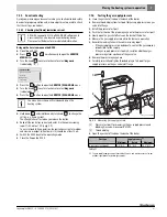
▶ Refit outer casing panels (
Fig. 49, page 38).
9.10.3 Confirming inspection or maintenance
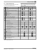
▶ Sign the inspection and maintenance report in this manual
(
Chapter 9.11, page 49).
4
1
2
3
3
2
P
P
B
I
C
E
1/2"
Ø1/4"
7747010720-87.02RS
E
1/2"
Ø1/4"
F
G
H
D
A
CAUTION:
Risk of system damage due to short-circuits!
▶ Cover the fan and other at-risk areas before
searching for leaks.
▶ Do not spray leak detector onto cable conduits, plugs
or electrical connecting cables. Do not let it drip onto
them either.
A PC with Logamatic ECO -Soft4000/EMS software and
a service key can also be used as a monitoring device.
Please contact Buderus for more detailed information.
Follow the instruction manuals for the BC10 and RC35.


