background image

Operation


- 3.54 - 

SMART 200 MTC


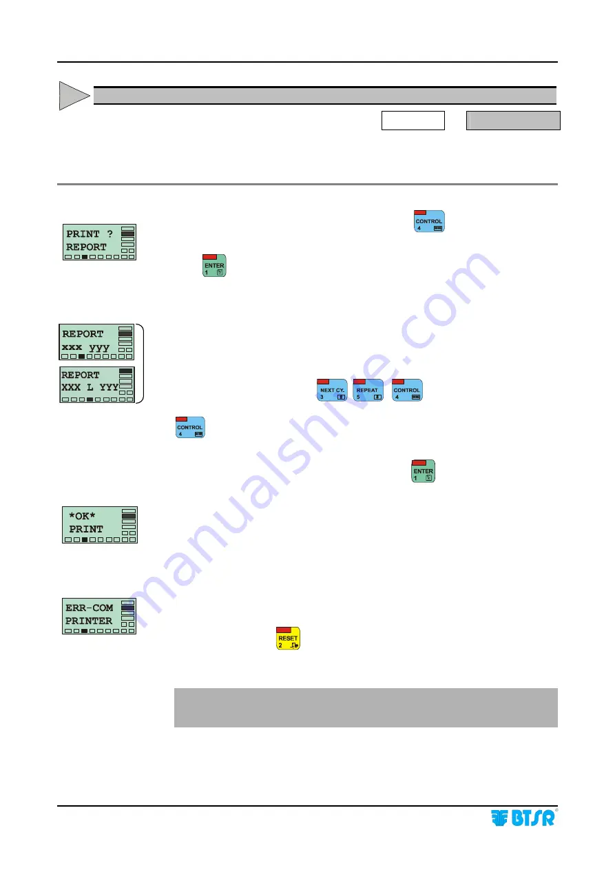
PRINT REPORT  -  Production Report Printing 

CONTROL 

  PRINT? REPORT

 
This function allows you to print a report containing the summary of  Failures 
(BK) and reached Targets (TG) for each machine position. 


During the counter visualization phase, pressing the 

  key, you will have 

access to the PRINT? REPORT function 

Press 

 to access the function. 


xxx = First sensor 

(position) 

to be included in the report 

yyy = Last sensor 

(position) 

to be included in the report 

L =  Machine Side (

either A or B

) if the SIDE function is active 

Select the desired range, using 

 , 


 3 sec = to select the desired machine side (either A or B), if the SIDE 

function is enabled. 

Once you have selected the desired positions, press 

 , to start the printout 


This screen indicates that the printout is in progress. 

When the printing is completed, the REPORT xxx, yyy screen will re-appear, 
allowing you to select a new sensor range for report printing. 


In case of communication error between SMART 200 MTC terminal and printer, 
an ERR_COM PRINTER error message will appear. 

At the end press once 

 to leave the function and return to screen or two times 

to return to Main Menu. 


The printout of “Production Report”, may also occur automatically, at the pre 
defined time, if the relevant TimePR option within the CLOCK menu has been 
programmed.


Summary of Contents for IS3W/MTC

Page 1: ...SMART 200 MTC IS3W MTC METER CONTROL SYSTEM Operating Manual Rev 2 0 September 2003 ENGLISH ...

Page 2: ...ny technical or commercial problem please contact your local BTSR dealer or call directly BTSR customer service center We will be glad to meet your needs Thank you for your trust and good job The product described herein is compliant with the requirements of 89 336 EEC EMC Directive and 73 23 EEC Low Voltage Directive All BTSR products are covered by patents and adopt exclusive profitable and high...

Page 3: ...TION SMART 200 MTC Terminal Features 3 1 IS3W MTC Sensor Features 3 4 Function of the IS3W MTC Sensors 3 4 Interface Characteristics 3 5 Interpretation of the signaling lights located on the sensors 3 7 Programmable Parameters 3 8 Parameters related to the Textile Machine Characteristics 3 8 Parameter that effect the sensor s detection and signaling characteristics 3 8 Parameters related to the SM...

Page 4: ...um Image Variation Frequency 3 45 DSTOP Sensor Reaction Time 3 46 SENS Sensor Sensitivity 3 47 MODIFY Modifying an existing Article 3 48 ERASE Erasing an existing Article 3 48 SCAN Displaying Articles currently loaded in the sensors 3 49 LOAD Loading an article to sensor memory 3 50 UNLOAD Unloading articles from the sensor memory 3 51 BAR GRAPH Graphic visualization of the Tension Detected by eac...

Page 5: ...tem according to the application needs Chapter 4 Troubleshooting and Maintenance provides a quick guide to solving the main technical faults of the system Appendix A Quick reference summarizes the sequence of operations that staff who have had sufficient experience in handling the system have to carry out in order to setup and program the system Symbols used Highlights notes warnings and points to...

Page 6: ...e choice while the small letters refer to the possible alternative choice Example Item Function Current Programming RES Ma Ma reset Manual RES mA Counter reset mode Automatic mA or Manual Ma mA reset Auto STP Cp Cp continuous signal STP cP STOP output programmable as continuous signal CONT pulse signal 2 seconds P2s or pulse signal 10 seconds P10s cP pulse signal ST NCo NCo normally closed ST NcO ...

Page 7: ...count both the physical characteristic of the machine drum development bobbin slipping etc and the characteristics of the article to be processed The measurement adjustment and control parameters can be programmed with utmost simplicity on the SMART 200 MTC Terminal and can be associated with a given article and saved to a database inside the terminal itself Depending on the article to be processe...

Page 8: ...achine General Features of SMART BTSR Systems Usage of IS3W electronic sensors Image Smart Scanning Sensor BTSR Patents The IS3W sensors can be connected to the SMART 200 MTC terminal using specific single connector cables Automatic Numbering BTSR Patents The identification of sensors is performed by the system by means of a quick automatic numbering procedure Multisensor System The system allows ...

Page 9: ...continuous or square signal 4Hz Target STOP output protection Protection against short circuits Maximum Current of STOP output 200 mA continuous 500 mA peak Vol STOP output 1 2 V with collector current 500 mA Signalling With integrated LEDs red and green Dimensions 25 x 15 x 36 5 Temperature range 0 60 C operation 25 85 C storage Installation The installation of the SMART 200 MTC system depends on...

Page 10: ...l Data and Installation 2 2 SMART 200 MTC Interface Connectors on SMART 200 MTC Concerning all electrical systems it is a recommended rule to ensure that the ground cable GND is connected to the sensor support ...

Page 11: ...ata and Installation SMART 200 MTC 2 3 Connection Example for Generic Applications Concerning all electrical systems it is a recommended rule to ensure that the ground cable GND is connected to the sensor support ...

Page 12: ...cm FE200 FEC Length 200 cm FE300 FEC Length 300 cm FE400 FEC Length 400 cm Doubler Cable from one Male to two Female with Independent Stop and Ground outputs to Connect a Alarm Signaling Light etc MA2FE3 Extension Cable 4x0 35 mm with Male and Female connector MA50 FEC Length 50 cm MA100 FEC Length 100 cm MA200 FEC Length 200 cm Connection cable with AMP male connector for single IS3W sensor MA35 ...

Page 13: ...e the adequate connection cable Open the rear cover of the sensor Plug the male connector of the cable into the Female connector of the sensor the reference key on the male connector must be positioned on the upper side of the connector Close the rear cover and secure the sensor using a M3 screw Check that the yarn can freely enter and exit the detection zone ...

Page 14: ...Technical Data and Installation 2 6 SMART 200 MTC Page intentionally left blank ...

Page 15: ...of straight forward messages which can be understood clearly and immediately On the top left hand side of each button there is a red LED which indicates that the button is pressed down The display screen includes two separate zones used respectively for displaying messages to the operator during the system programming and administration phases and for signaling the operating status and levels in w...

Page 16: ...s displayed where the cursor is located according to the following cyclic sequence When entering numeric data for example the number of sensors it allows the increase of numeric value of the field If it is held down continuously the numeric field increments more rapidly 4 CONTROL button During parameter programming it allows changing the position of the cursor 5 REPEAT button During navigation wit...

Page 17: ... hand side of the operator message area 6 rectangular boxes labels are implemented They display the operating status of the system More specifically the PROGRAM label indicates that you are operating in one of the following modes configuration programming or data transmission to the sensors The CONTROL label indicates that the system is operating normally with all monitor functions enabled and acc...

Page 18: ...e to the quality control of any type of yarn Function of the IS3W MTC Sensors The IS3W sensors allow the real time detection of strokes i e the crossings of yarn within the optical reading zone and stop the position when reaching the set TARGET furthermore if properly programmed they can detect the yarn broken missing condition The IS3W sensors have two signaling lights green LED and red LED and a...

Page 19: ... STOP output can be configured either as a Normally Open ST NcO contact or as a Normally Closed ST NCo contact while for what concerns the timing it can be configured either as a continuous signal ST Cp or as a 2 seconds 10 seconds pulse signal ST cP to indicate a failure condition and as a continuous signal STG CT or as a 4 Hz square signal STG SQ to indicate the Target reached condition Starting...

Page 20: ... Condition Signal Configuration Failure Yarn Broken ST Cp Failure Yarn Broken ST cP 2 sec Failure Yarn Broken ST cP 10 sec Target Reached STG CT Target Reached STG SQ Normally Open ST NcO Contact Failure Yarn Broken ST Cp Failure Yarn Broken ST cP 2 sec Failure Yarn Broken ST cP 10 sec Target Reached STG CT Target Reached STG SQ Normally Closed ST NCo Contact B Yarn Broken T Target ...

Page 21: ...ation the sensor has detected a failure broken yarn and currently the yarn is steady Green LED ON Red LED ON Stopped sensor Switch off then switch on the system If the condition is permanent replace the sensor Green LED OFF Red LED OFF Sensor not powered Green LED BLINKING Red LED BLINKING 1 TARGET reached 2 Fault in the sensor e g a loss of data You must re program the device This type of failure...

Page 22: ...ication STG Stop output when reaching the Target for further information please refer to the previous paragraph Interfacing Specification These parameters are normally defined during the system installation step and unless exceptional cases they should not be changed Parameters related to the SMART 200 MTC system operation RES Counters reset mode either Automatic or Manual STE on off Possibility t...

Page 23: ...splicing then 5 meters will be subtracted to the count for every breakage occurred Parameter related to the article being processed that affect the sensor s detection characteristics DSTART Activation delay It defines the minimum image variation frequency above which the sensor indicates a stroke detection It can be programmed using a value ranging between 1 minimum frequency and 10 maximum freque...

Page 24: ...the SMART terminal Press to reset the error The system will erase all settings entered by the user and will reload the default values If the error persists please refer to Troubleshooting chapter If the system displays one of the screen that you can see on the left side it means that the terminal is working correctly and that it is possible to activate one of the four options of the main menu If n...

Page 25: ...position controlled by a IS3W sensor printing out the production report upon operator command or automatically at predefined intervals Article loading unloading i e the settings related to the articles into the connected sensors and counter resetting from SMART terminal Displaying in graphical form the number of meters wound for each position controlled by an IS3W sensor The main menu of the syste...

Page 26: ...Operation 3 12 SMART 200 MTC Enabling the SETUP Menu Functions ...

Page 27: ...Operation SMART 200 MTC 3 13 Enabling the SETUP Menu Functions NEW MODIFY ERASE Enabling the WORK Menu Functions ...

Page 28: ...Operation 3 14 SMART 200 MTC Enabling the GRAPH Menu Functions ...

Page 29: ...ng D TOT L TG xxx DEV TOT TG xxx Number of Targets reached Total D TOT L BK xxx DEV TOT BK xxx Number of yarn breakage failures Total D nnn L TG xxx DEV nnn TG xxx Number of Targets reached on device nnn D nnn L BK xxx DEV nnn BK xxx Number of yarn breakage failures on device nnn ...

Page 30: ...MART 200 MTC By pressing or it is possible to either increase or decrease the XXX value until reaching the number of sensors actually connected to the system At this point press to start the numbering operation This screen indicates that the phase of automatic sensor numbering is starting YYY shows the total amount of sensors to be numbered ZZZ shows the number of the first sensor and subsequently...

Page 31: ...dded sensor using and Replacing a Sensor Example 1 If the machine has 12 sensors and the sensor No 8 has been replaced the display will show this data Press until the right field where the cursor is positioned shows 008 With a finger skim the Touch Light area of the sensor No 8 and check that the sensor LED changes from flashing green to red The replaced sensor will now be identified as sensor No ...

Page 32: ...SIDE disabled Sensors 1 2 3 98 99 100 2 Number of installed sensors 100 option SIDE enabled Sensors 1A 2A 3A 48A 49A 50A 1B 2B 3B 48B 49B 50B Once you have selected the SIDE function from CONFIG menu press to have access to the function If necessary press to select the desired option SIDE A B machine logically subdivided into 2 sides A and B SIDE OFF logically subdivision disabled OFF Press to con...

Page 33: ... on Chapter 4 for more details Once you have selected the LDRUM function from CONFIG menu press to have access to the function XX indicates the sensor s number AAAA indicates the length development of drum in mm L A or B if the SIDE option is enabled moves the cursor from XX field to AAAA field and vice versa if the SIDE option is disabled or from XX field to L field to AAAA field and vice versa i...

Page 34: ...hich you want to set the same LDRUM value increases the value of yyy field Once you have set the desired range press to continue The DEV XX AAAAmm or D XX L AAAAmm screen will re appear Repeat the previous operation if you want to choose a new LDRUM value and a new interval of sensors until all the sensors will be assigned a LDRUM value At the end press to continue Saving the LDRUM values into the...

Page 35: ...u have selected the LDRUM function from CONFIG menu press to have access to the function XX indicates the sensor s number nn n indicates the correction factor 12 5 to 12 5 L A or B if the SIDE option is enabled moves the cursor from xx field to nn n field and vice versa if the SIDE option is disabled or from xx field to L field to nn n field and vice versa if the SIDE option is enabled 3sec Switch...

Page 36: ...ch you want to set the same KANTIP value increases the value of yyy field Once you have set the desired range press to continue The DEV xx nn n or D xx L nn n screen will re appear Repeat the previous operation if you want to choose a new KANTIP value and a new interval of sensors until all the sensors will be assigned a KANTIP value At the end press to continue Saving the KANTIP values into the s...

Page 37: ... the function is disabled BK Off the sensor will operate as meter counter only Once you have selected the BK On Off function from CONFIG menu press to have access to the function If necessary press to select the desired option either BK On CONFIG or BK Off CONFIG Press to confirm The display shows for a few seconds the messages BK On WAIT and BK On PRG OK or BK Off WAIT and BK Off PRG OK to indica...

Page 38: ... TARGET the counter will still be incremented if further strokes occur RESET AUTO Automatic Counter Reset When reaching the TARGET the counter is automatically reset by the next stroke This is the mode typically used on automatic machines The sensor continues to count the strokes until it detects a machine steady condition no more strokes When the sensor detects a new stroke it resets the counter ...

Page 39: ...chosen for the STP NCo function For more details please refer to the Interface Specifications STOP signal paragraph Once you have selected the STP xx function from CONFIG menu press to have access to the function If necessary press to select the desired option ST CONT CONFIG ST P2s CONFIG or ST P10s CONFIG Press to confirm The display shows for a few seconds the messages ST CONT WAIT and ST CONT P...

Page 40: ...nal is connected to a machine computer as it gives the computer itself the possibility to distinguish between a Target reached stop and a failure stop For more details please refer to the Interface Specifications STOP signal paragraph Once you have selected the STG xx function from CONFIG menu press to have access to the function If necessary press to select the desired option CONT CONFIG or SQUAR...

Page 41: ...gnal operation please refer to the Interface Specification paragraph STOP Signal Once you have selected the ST XxX function from CONFIG menu press to have access to the function If necessary press to select the desired option STOP NO CONFIG or STOP NC CONFIG Press to confirm the selection The display shows for a few seconds the messages STOP NO WAIT and STOP NO PRG OK or STOP NC WAIT and STOP NC P...

Page 42: ...gured as Normally Open ST NcO contact Function available starting from Software version 4 0 Once you have selected the STE xx function from menu press to have access to the function If necessary press to select the desired option STE On CONFIG or STE Off CONFIG Press to confirm the selection The display shows for a few seconds the messages STE On WAIT and STE On PRG OK or STE Off WAIT and STE Off ...

Page 43: ...om 1 to 7 alphanumeric characters using the following buttons Increases the character where the cursor is positioned Decreases the character where the cursor is positioned Moves the cursor one position to the right Confirms and stores the code which has been set If no code is entered the function is disabled and you will not be asked for an access code when entering the CONFIG SETUP menu Press onc...

Page 44: ...om 1 to 7 alphanumeric characters using the following buttons Increases the character where the cursor is positioned Decreases the character where the cursor is positioned Moves the cursor one position to the right Confirms and stores the code which has been set If no code is entered the function is disabled and you will not be asked for an access code when entering the WORK menu Press once to ret...

Page 45: ...R Reading the times set for the automatic printout of production reports adding changing or erasing one or more fixed times up to a maximum of four for automatic printout of production reports Once you have selected the KEY ST function from menu press to have access to the submenu of the available functions Use to select the desired function and confirm using RTCSET RTC Reading Setting Once you ha...

Page 46: ...e TimePR function from CLOCK menu press to have access to the function N progressive number within the set time table 1 to 4 HH MM Read values HH hours MM minutes New values Press to display the next value after the fourth value the firs one will re appear Press twice to leave the function and return to the CLOCK menu without saving the values being a read only operation TimePR Adding a time for t...

Page 47: ...t the operation to add other times for the automatic printout TimePR Changing a time for automatic printout of Production Report If you want to change an existing time select the time to be changed using or Press to activate the function Change the value using Increases the value pointed by the cursor Decreases the value pointed by the cursor Moves the cursors from HH to MM fields and vice versa C...

Page 48: ...he time to be erased then press and subsequently press and hold down for 3 seconds The selected field will be erased and replaced by N Press to leave the function with the possibility to save the new situation saves the new situation and returns to the CLOCK menu leaves the function and returns to the CLOCK menu without saving If necessary repeat the operation to erase other times for the automati...

Page 49: ...This screen indicates that the sensor test is going to start Press to continue DEV XXX or L XXX if the SIDE option is enabled indicates the sensor which is being tested initially sensor no 1 Check that the Red LED of sensor XXX is flashing and there are no other sensors with the Red LED FLASHING If the Red LED of the sensor that should respond to the number XXX is not flashing it means that the se...

Page 50: ... signaled by the sensors Once you have selected the TEST function from CONFIG menu press to have access to the function Press to select the Communications Test This screen indicates that the Communications Test is going to start Press to begin the test From this moment on the system communicates repeatedly with all connected sensors The running test status is signaled by the flashing red LED insid...

Page 51: ...u have selected the TEST function from CONFIG menu press to have access to the function Press until the VERS TEST menu item appears Press to continue DEV XXX or D XXX A if the SIDE option is enabled Number of IS3W device L Machine Side if the SIDE option is enabled n n Software version loaded on xxx device Press to select in sequence all the connected devices and check the software version loaded ...

Page 52: ...nabled Press and hold down for 3 seconds to switch from Side A to Side B and vice versa Select the range of sensors to be updated using Press to execute the updating The selected sensors will be automatically updated one after the other and the field xxx will automatically increase until it reaches the value set in yyy in the previous step Press once to leave this function or press it twice to ret...

Page 53: ...the default ones Article TARGET 1 9999999 0000050 Parameter Possible Values K_ 12 5 12 5 0 0 K_MET 100 m 100 m 0 0 m DCOUNT 1 100 ms 25 ms DSTART 01 10 03 DSTOP 5 10 20 50 100 200 500 1000 ms 500 ms SENS 01 10 06 Once you have selected the NEW function on the SETUP menu you are prompted to enter the name of the new article Type the name using to set the characters and use to move the cursor If you...

Page 54: ...Operation 3 40 SMART 200 MTC At this point you will have to program in sequence the contol parameters related to the article being created TARGET K_ K_MET DCOUNT DSTART DSTOP SENS ...

Page 55: ...hed the counter will be reset either manually or automatically depending on the RES M A parameter setting in the CONFIG menu Once you have selected the TARGET function from NEW menu press to have access to the function Set the desired value using and Increment by 1 Decrement by 1 hold down Continuous increment hold down Continuous decrement hold down Fast increment hold down Fast decrement Confirm...

Page 56: ... will be calculated according to the following formula Number of strokes KANTIP K_ Example If Target 10000 m LDRUM 500 m KANTIP 5 e K_ 2 then number of strokes 20000 1000 400 20600 Once you have selected the K_ function from NEW menu press to have access to the function Set the desired value using and Increment by 0 1 Decrement by 0 1 hold down Continuous increment hold down Continuous decrement h...

Page 57: ...ic splicing system of the textile machine The parameter may range from 100 0 m to 100 0 m with 0 1 meter resolution Once you have selected the K MET function from NEW menu press to have access to the function Set the desired value using and Increment by 0 1 Decrement by 0 1 hold down Continuous increment hold down Continuous decrement hold down Fast increment hold down Fast decrement Confirms the ...

Page 58: ... or false counts Usually the DCOUNT parameter should be programmed according to the collection speed with a value corresponding to 50 of the time interval between two strokes stroke frequency It may range between 1ms and 100ms DCOUNT operation example Once you have selected the DCOUNT function from NEW menu press to have access to the function Set the desired value using and Increment by 1 Decreme...

Page 59: ...ction The sensor through a wrap around buffer covering a time interval of 5ms constantly check that within the last 5ms the number of image variations occurred is at least equal to the value set through the DSTART parameter It can be programmed with a value ranging between 01 minimum frequency and 10 maximum frequency Once you have selected the DSTART function from NEW menu press to have access to...

Page 60: ...med with values ranging between 5 ms and 1000 ms according to the following sequences 5ms 10ms 20ms 50ms 200ms 500ms 1000ms Once you have selected the DSTOP function from NEW menu press to have access to the function Set the desired value using and Selects the next value Selects the previous value Confirms the set value Clears the set value restores the previous value and returns to DSTOP screen O...

Page 61: ...rocessed that effect the sensor s detection characteristics paragraph on page 3 9 Once you have selected the SENS function from NEW menu press to have access to the function Set the desired value using and Increment by 1 Decrement by 1 Confirms the set value Clear the set value restores the previous value and returns to SENS screen SENS is the last programmable parameter of the article created To ...

Page 62: ...e data base using 2 During the saving step you will have the possibility to save the modified article with a new name AAA SAVE AS ERASE Erasing an existing Article SETUP ERASE This function allows you to remove from the data base a previously created article Press to have access to the function Select the article to be removed using and press to continue Press to confirm the erase function During ...

Page 63: ...rticular YYY shows the first sensor on which the article has been loaded KKK shows the last sensor on which the article has been loaded L indicates the machine side either A or B if the SIDE option is enabled Press to select to the next article When the scanning of all the articles currently loaded has finished the END SCAN message appears to indicate that there are no other articles beyond those ...

Page 64: ...the cursor between XXX and YYY fields Press and hold down for 3 seconds to switch from Side A to Side B and vice versa if the SIDE option is enabled Press to confirm the setting and go to the next screen Press to load the parameters of the article in the selected range of sensors During the loading phase the message OK WAIT LOAD is shown for a few seconds If you try to load an article into a range...

Page 65: ...on Press once or several times until the name of the required article that you wish to unload from the sensor appears YYY KKK sensor interval from which to unload the article L indicates the machine side either A or B if the SIDE option is enabled At this point press to have access to the function Press to unload the settings of the article from the sensors which were previously detecting that art...

Page 66: ...label start blinking Once you have selected the GRAPH item from Main menu press to have access to the function Press to activate the graphic display BAR To increase the device number To decrease the device number To quit the function If the SIDE function is active then the DEV 01 indication will become DEV 01 A or DEV 01 B To switch between A and B press CONTROL Status indicator of the count progr...

Page 67: ...he TARGET the status indicator and the TARGET label start blinking Once you have selected the GRAPH item from main menu press to have access to the function Press to select the ISTOG GRAPH function Press to have access to function Choose the reference device XXX using 3 sec to select the desired machine Side either A or B if the SIDE option is enabled Press to activate the graphic display ISTOG Pr...

Page 68: ...d range using 3 sec to select the desired machine side either A or B if the SIDE function is enabled Once you have selected the desired positions press to start the printout This screen indicates that the printout is in progress When the printing is completed the REPORT xxx yyy screen will re appear allowing you to select a new sensor range for report printing In case of communication error betwee...

Page 69: ...Operation SMART 200 MTC 3 55 Production Report Example ...

Page 70: ...Operation 3 56 SMART 200 MTC Page intentionally left blank ...

Page 71: ...If the problem persists repeat the sensor numbering procedure The sensor numbering procedure fails the number YYY does not increase in the screen DEV Y XXX YYY Problems on the communications line Check that the sensors are correctly connected Check for locked sensors green and red LED simultaneously ON Power off and on the system If the problem persists replace the sensor If the problem persists c...

Page 72: ...detection features to remain unaffected even when some traces of dirt are present However it is suggested to clean the sensors periodically For maintenance operations on printer device i e paper roll replacement please refer to the operating manual supplied with the printer itself For cleaning purposes do not use solvent but rather a soft cloth dampened with neutral detergent or alcohol Repairs An...

Page 73: ...e positions in order to obtain an average value 1 Program the desired sensor with a LDRUM value equal to 1000 in this way the sensor will increment the counter by 1 unit upon each stroke 2 Program the TARGET value of the sensor with a very large number in order to prevent the sensor from stopping the machine because of TARGET reached 3 Reset the sensor s stroke counter using the Touch Light and co...

Page 74: ...nter value Menu COUNT let s suppose that the value read is CNT1 189 000 sensors stroke counter 5 Using the appropriate conversion formula obtain the length in meters corresponding to 1000 g of silk 21 deniers Meters_Weighti 9000 Pi 9000 1000 428571 meters Title deniers 21 6 Now we can calculate the LDRUM value using the following formula LDRUMi 1000 Meters_Weighti 1000 428571 2268 mm stroke CNTi 1...

Page 75: ...ew the 4 locking screws and remove the rear cover Fig 1 6 Using the IC extractor remove with care the Integrated Circuit from the socket located on the right top corner of PCB Fig 2 7 Place the Integrated Circuit containing the new software version over the socket paying attention to its correct orientation Fig 3 8 Applying a moderate and progressive pressure with both thumbs push the integrated c...

Page 76: ...onfiguration values it is suggested to take note of the defined settings for each article which have been created The following tables are intended to help you in this task Article TARGET Parameter Set Value K_ K_MET DCOUNT DSTART DSTOP SENS Article TARGET Parameter Set Value K_ K_MET DCOUNT DSTART DSTOP SENS Article TARGET Parameter Set Value K_ K_MET DCOUNT DSTART DSTOP SENS ...

Page 77: ...vailable on the SMART 200 MTC system The use of the quick reference guide supposes that the user has already acquired a certain ability in handling the system therefore there are no detailed explanations of each screen shot there is only a global overview of sequences of the required steps for each function For an explanation of the symbols used in the quick reference guide please refer to Symbols...

Page 78: ...Appendix A Quick Reference Symbols Key A 2 SMART 200 MTC ...

Page 79: ...Appendix A Quick Reference Symbols Key SMART 200 MTC A 3 ...

Page 80: ...Appendix A Quick Reference Symbols Key A 4 SMART 200 MTC NO NC ...

Page 81: ...Appendix A Quick Reference Symbols Key SMART 200 MTC A 5 ...

Page 82: ...Appendix A Quick Reference Symbols Key A 6 SMART 200 MTC ...

Page 83: ...Appendix A Quick Reference Symbols Key SMART 200 MTC A 7 ...

Page 84: ...Appendix A Quick Reference Symbols Key A 8 SMART 200 MTC ...

Page 85: ...Appendix A Quick Reference Symbols Key SMART 200 MTC A 9 ...

Page 86: ...Appendix A Quick Reference Symbols Key A 10 SMART 200 MTC ...

Page 87: ...Appendix A Quick Reference SMART 200 MTC A 11 Notes ...

Page 88: ...Appendix A Quick Reference A 12 SMART 200 MTC Page intentionally left blank ...

Page 89: ...BTSR International S p A Via S Rita 21057 OLGIATE OLONA VA Tel 0331 323202 Fax 0331 323282 Internet www btsr com REV 2 0 09 03 DISTRIBUTOR ...

Reviews: