CHAPTER 6 TROUBLESHOOTING
6-46
I-15
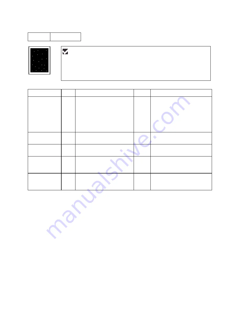
White spots
Possible cause
Step
Check
Result
Remedy
Drum unit failure
1
Are the white spot at 94mm
intervals?
Yes
1) If toner or glue remains
stuck, wipe it off gently with a
cotton swab. (Refer to
NOTE
in the next page.)
2) If the drum surface is
scratched, replace the drum
unit.
Drum unit failure
2
Is the problem solved after
replacing the drum unit?
Yes
Replace the drum unit.
No toner
3
Is the toner in the toner
cartridge almost empty?
Yes
Replace the toner cartridge with
a new one.
Print paper
4
Is the problem solved after
changing to specified freshly
unpacked paper?
Yes
Damp (wet) paper might be
used. Recommend to change
freshly unpacked paper.
Environment
5
Does the problem still appear
after the printer has warmed
up?
Yes
1) Replace the drum unit.
2) Advise the user of the
specified print environment.
User Check
(1) If the problem is not solved after printing a few pages, the drum unit may have
glue from label stock on the photosensitive drum surface. Refer to Step 1 in the
table below and
NOTE
in the next page.
(2) The drum unit may be damaged. Install a new drum unit.
Summary of Contents for HL-1870N
Page 15: ...HL 1850 1870N SERVICE MANUAL xiii ...
Page 77: ...CHAPTER 2 INSTALLATION AND BASIC OPERATION 2 48 ...
Page 82: ...HL 1850 1870N SERVICE MANUAL 3 5 Fig 3 5 ...
Page 91: ...CHAPTER 3 THEORY OF OPERATION 3 14 Fig 3 15 ...
Page 101: ...CHAPTER 3 THEORY OF OPERATION 3 24 ...
Page 109: ...CHAPTER 4 DISASSEMBLY AND RE ASSEMBLY 4 2 ...
Page 131: ...CHAPTER 4 DISASSEMBLY AND RE ASSEMBLY 4 24 Fig 4 39 ...
Page 141: ...CHAPTER 4 DISASSEMBLY AND RE ASSEMBLY 4 34 Never touch the surface of the heat roller ...
Page 148: ...CHAPTER 4 DISASSEMBLY AND RE ASSEMBLY 4 41 ...
Page 158: ...CHAPTER 4 DISASSEMBLY AND RE ASSEMBLY 4 51 Fig 4 80 ...
Page 160: ...CHAPTER 4 DISASSEMBLY AND RE ASSEMBLY 4 53 Fig 4 82 ...
Page 167: ...CHAPTER 4 DISASSEMBLY AND RE ASSEMBLY 4 60 Fig 4 91 ...
Page 169: ...CHAPTER 4 DISASSEMBLY AND RE ASSEMBLY 4 62 Fig 4 93 ...
Page 172: ...CHAPTER 4 DISASSEMBLY AND RE ASSEMBLY 4 65 Fig 4 97 ...
Page 174: ...CHAPTER 4 DISASSEMBLY AND RE ASSEMBLY 4 67 3 27 Harness Winding Form ...
Page 183: ...CHAPTER 5 PERIODIC MAINTENANCE 5 8 ...
Page 186: ...HL 1850 1870N SERVICE MANUAL 5 11 ...
Page 194: ...CHAPTER 6 TROUBLESHOOTING 6 8 error in this chapter ...
Page 202: ...CHAPTER 6 TROUBLESHOOTING 6 16 ...
Page 205: ...HL 1850 1870N SERVICE MANUAL 6 19 ...
Page 210: ...CHAPTER 6 TROUBLESHOOTING 6 24 ...
Page 237: ...HL 1850 1870N SERVICE MANUAL 6 51 No Refer and compare with I 15 ...
Page 255: ...HL 1850 1870N SERVICE MANUAL 6 69 ...
Page 261: ...CHAPTER 7 HIDDEN FUNCTIONS 7 6 DRAM CHECK START START DRAM TEST Tests DRAM data ...
Page 270: ...HL 1850 1870N SERVICE MANUAL 7 15 ...
Page 271: ......
Page 272: ...Appendix 1 Connection Diagram HL 1850 1870N A 1 ...
Page 273: ...Appendix 2 Main PCB Circuit Diagram HL 1850 1870N 1 6 CODE LJ8453001 B512078CIR 1 6 A 2 NAME ...
Page 274: ...Appendix 3 Main PCB Circuit Diagram HL 1850 1870N 2 6 CODE LJ8453001 B512078CIR 2 6 A 3 NAME ...
Page 275: ...Appendix 4 Main PCB Circuit Diagram HL 1850 1870N 3 6 CODE LJ8453001 B512078CIR 3 6 A 4 NAME ...
Page 276: ...Appendix 5 Main PCB Circuit Diagram HL 1850 1870N 4 6 CODE LJ8453001 B512078CIR 4 6 A 5 NAME ...
Page 277: ...Appendix 6 Main PCB Circuit Diagram HL 1850 1870N 5 6 CODE LJ8453001 B512078CIR 5 6 A 6 NAME ...
Page 278: ...Appendix 7 Main PCB Circuit Diagram HL 1850 1870N 6 6 CODE LJ8453001 B512078CIR 6 6 A 7 NAME ...
Page 284: ...Appendix 13 High voltage Power Supply PCB Circuit Diagram A 13 NAME High voltage PS Circuit ...
Page 303: ...APPENDIX A 32 ...


