APPENDIX
A-19
2.
How to Read the Drum Unit Life
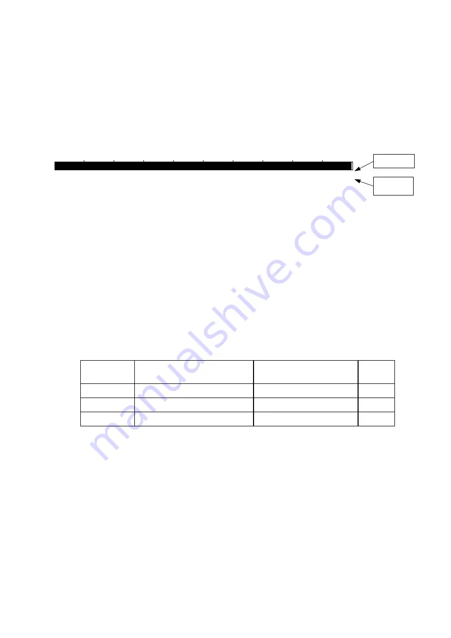
The drum unit life is shown by the bar at the bottom of Print Configuration or Test Print as
follows;
•
It initially indicates 100% and gradually decreases.
•
It indicates 0% when the CHANGE DRUM SOON message appears on the LCD display
on the control panel.
•
It stays at 0% even if further printing is done.
Drum Life
00000020202020202
100%
0%
99.9%
MZ-L2000000006801
Fig. A-2
The drum unit life is based on the page counter. If the average number of drum rotations is
more than the number of drum rotations in non-continuous printing, however, the drum unit life
is counted by the number of drum rotations.
Since the drum counter printed in Print Configuration is an actual page counter after a new
drum unit is replaced, the drum unit life may be different from the drum counter.
For details on the difference between the drum unit life and drum counter, refer to the drum unit
life calculation below;
<How to calculate drum unit life>
**Printing time for 1 page/job in discontinuous printing = 12 seconds
(Page counter reduced by the number of drum rotations) = (Time of motor rotation) ÷ (12 sec.)
Example:
Cold start (Idling for 6 sec.)
Hot start
Page
counter
1 page/job
(6 + 8.4) / 8.4 = 1.71
8.4 / 8.4 = 1
1
2 pages/job
(6 + 8.4 + 3.3) / 8.4 = 2.11
(8.4 + 3.3) / 8.4 = 1.39
2
16 pages/job
(6 + 8.4 + 3.3 x 17) / 8.4 = 8.39
(8.4 + 3.3 x 17) / 8.4 = 7.68
18
If printing 1 page per job with cold start, the drum unit life is decreased earlier.
NOTE:
For information on how to understand the numbers on the right below the bar, see the following
sections,
3. How to Read the Page Counter
and
4. How to Read the Maintenance
Information
.
Page counter
Maintenance
information
Summary of Contents for HL-1870N
Page 15: ...HL 1850 1870N SERVICE MANUAL xiii ...
Page 77: ...CHAPTER 2 INSTALLATION AND BASIC OPERATION 2 48 ...
Page 82: ...HL 1850 1870N SERVICE MANUAL 3 5 Fig 3 5 ...
Page 91: ...CHAPTER 3 THEORY OF OPERATION 3 14 Fig 3 15 ...
Page 101: ...CHAPTER 3 THEORY OF OPERATION 3 24 ...
Page 109: ...CHAPTER 4 DISASSEMBLY AND RE ASSEMBLY 4 2 ...
Page 131: ...CHAPTER 4 DISASSEMBLY AND RE ASSEMBLY 4 24 Fig 4 39 ...
Page 141: ...CHAPTER 4 DISASSEMBLY AND RE ASSEMBLY 4 34 Never touch the surface of the heat roller ...
Page 148: ...CHAPTER 4 DISASSEMBLY AND RE ASSEMBLY 4 41 ...
Page 158: ...CHAPTER 4 DISASSEMBLY AND RE ASSEMBLY 4 51 Fig 4 80 ...
Page 160: ...CHAPTER 4 DISASSEMBLY AND RE ASSEMBLY 4 53 Fig 4 82 ...
Page 167: ...CHAPTER 4 DISASSEMBLY AND RE ASSEMBLY 4 60 Fig 4 91 ...
Page 169: ...CHAPTER 4 DISASSEMBLY AND RE ASSEMBLY 4 62 Fig 4 93 ...
Page 172: ...CHAPTER 4 DISASSEMBLY AND RE ASSEMBLY 4 65 Fig 4 97 ...
Page 174: ...CHAPTER 4 DISASSEMBLY AND RE ASSEMBLY 4 67 3 27 Harness Winding Form ...
Page 183: ...CHAPTER 5 PERIODIC MAINTENANCE 5 8 ...
Page 186: ...HL 1850 1870N SERVICE MANUAL 5 11 ...
Page 194: ...CHAPTER 6 TROUBLESHOOTING 6 8 error in this chapter ...
Page 202: ...CHAPTER 6 TROUBLESHOOTING 6 16 ...
Page 205: ...HL 1850 1870N SERVICE MANUAL 6 19 ...
Page 210: ...CHAPTER 6 TROUBLESHOOTING 6 24 ...
Page 237: ...HL 1850 1870N SERVICE MANUAL 6 51 No Refer and compare with I 15 ...
Page 255: ...HL 1850 1870N SERVICE MANUAL 6 69 ...
Page 261: ...CHAPTER 7 HIDDEN FUNCTIONS 7 6 DRAM CHECK START START DRAM TEST Tests DRAM data ...
Page 270: ...HL 1850 1870N SERVICE MANUAL 7 15 ...
Page 271: ......
Page 272: ...Appendix 1 Connection Diagram HL 1850 1870N A 1 ...
Page 273: ...Appendix 2 Main PCB Circuit Diagram HL 1850 1870N 1 6 CODE LJ8453001 B512078CIR 1 6 A 2 NAME ...
Page 274: ...Appendix 3 Main PCB Circuit Diagram HL 1850 1870N 2 6 CODE LJ8453001 B512078CIR 2 6 A 3 NAME ...
Page 275: ...Appendix 4 Main PCB Circuit Diagram HL 1850 1870N 3 6 CODE LJ8453001 B512078CIR 3 6 A 4 NAME ...
Page 276: ...Appendix 5 Main PCB Circuit Diagram HL 1850 1870N 4 6 CODE LJ8453001 B512078CIR 4 6 A 5 NAME ...
Page 277: ...Appendix 6 Main PCB Circuit Diagram HL 1850 1870N 5 6 CODE LJ8453001 B512078CIR 5 6 A 6 NAME ...
Page 278: ...Appendix 7 Main PCB Circuit Diagram HL 1850 1870N 6 6 CODE LJ8453001 B512078CIR 6 6 A 7 NAME ...
Page 284: ...Appendix 13 High voltage Power Supply PCB Circuit Diagram A 13 NAME High voltage PS Circuit ...
Page 303: ...APPENDIX A 32 ...


