HE-800B
5. MECHANICAL DESCRIPTIONS
36
5. MECHANICAL DESCRIPTIONS
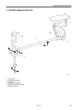
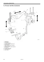
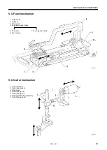
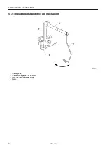
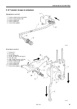
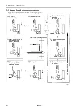
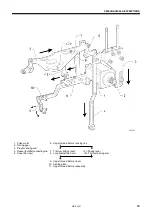
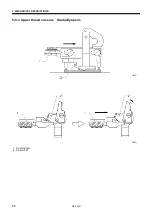
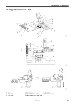
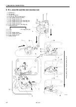
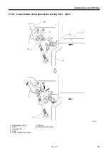
* <number> and [number] indicates the flow of each operations given.
* (number) indicates part names only. (They do not represent the flow of operations.)
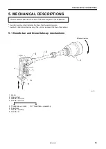
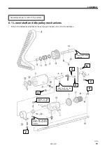
5-1. Needle bar and thread take-up mechanisms
1. Motor
2. Upper shaft
3. Needle bar crank
4. Needle bar crank
5. Thread take-up crank
<5>
Thread take-up assembly
6. Slide block
7. Needle bar clamp
8. Needle bar
The mechanisms operate in the order of the numbers given in the illustrations.
0641D
Rotation direction
Summary of Contents for HE-800B
Page 7: ...v HE 800B Oil tank accessory 4732M 4731M 4730M ...
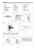
Page 75: ...6 ASSEMBLY HE 800B 66 D E 0688D 0690D ...
Page 126: ...9 ELECTRIC MECHANISM HE 800B 117 Power PCB Cutter PCB LCD panel PCB 0831D 0768D 0769D ...
Page 133: ...9 ELECTRIC MECHANISM HE 800B 124 0851D ...
Page 134: ...9 ELECTRIC MECHANISM HE 800B 125 0852D ...
Page 135: ...9 ELECTRIC MECHANISM HE 800B 126 0853D ...
Page 177: ...MEMO 168 HE 800B ...
Page 178: ...SERVICE MANUAL 2014 Brother Industries Ltd All Rights Reserved HE 800B I3061003D 2014 03 D 1 ...

