6. ASSEMBLY
HE-800B
51
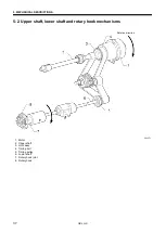
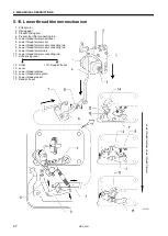
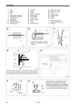
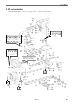
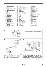
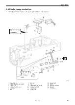
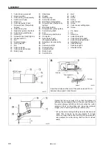
1. Wick
2. Collar
3. Wick
4. Felt
5. Rotary hook shaft bush
6. Rotary hook felt support
7. Screws [2 pcs]
8. Timing belt
9. Retaining ring
10. Ball bearing [2 pcs]
11. Retaining ring
12. Idle pulley
13. Collar
14. Shaft
15. Set screws [2 pcs]
16. Bush assy M
17. Timing pulley
18. Lower shaft
19. Set screw collar
20. Wick
21. Spring
22. Rotary hook felt
23. Set screws [2 pcs]
24. Set screws [2 pcs]
25. Cover
26. Screws [2 pcs]
27. Rubber presser
28. Spring
29. Screw
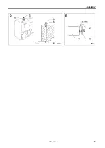
a. Rubber plugs [4 pcs]
b. Oil feeding pipe [4 pcs]
c. Bearing
A
B
C
D
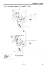
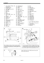
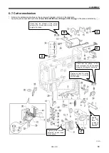
Check that the spring (20) is not compressed when the wick
(21) is pulled in the direction of the arrow. Push the end of the
felt (22) into the hole in the bush (5) and stop it from turning.
E
F
G
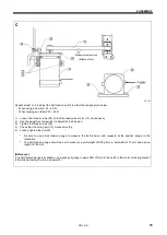
As a guide for the lubrication amount, the
optimum position can be obtained if the
screw (29) is tightened as much as possible
and then loosened about two turns. Refer to
“7-19. Adjusting the rotary hook lubrication”
to check and adjust the lubrication amount.
0665D
0668D
0667D
0669D
0664D
0660D
0666D
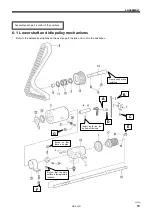
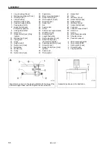
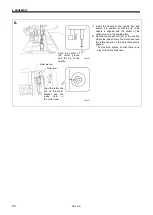
Push in the felt (4) so that the
wick (3) is touching the lower
shaft (18).
Summary of Contents for HE-800B
Page 7: ...v HE 800B Oil tank accessory 4732M 4731M 4730M ...
Page 75: ...6 ASSEMBLY HE 800B 66 D E 0688D 0690D ...
Page 126: ...9 ELECTRIC MECHANISM HE 800B 117 Power PCB Cutter PCB LCD panel PCB 0831D 0768D 0769D ...
Page 133: ...9 ELECTRIC MECHANISM HE 800B 124 0851D ...
Page 134: ...9 ELECTRIC MECHANISM HE 800B 125 0852D ...
Page 135: ...9 ELECTRIC MECHANISM HE 800B 126 0853D ...
Page 177: ...MEMO 168 HE 800B ...
Page 178: ...SERVICE MANUAL 2014 Brother Industries Ltd All Rights Reserved HE 800B I3061003D 2014 03 D 1 ...

