6. ASSEMBLY
HE-800B
55
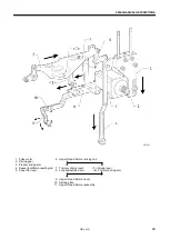
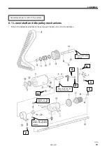
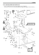
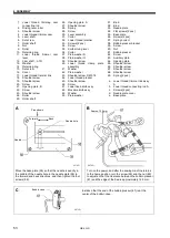
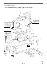
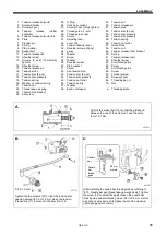
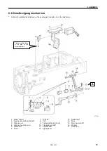
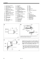
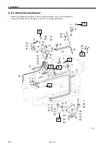
1. Linear bushing [2 pcs]
2. Ball bearing stoppers [2 pcs]
3. Screws [2 pcs]
4. Linear bushing
5. Retaining rings [2 pcs]
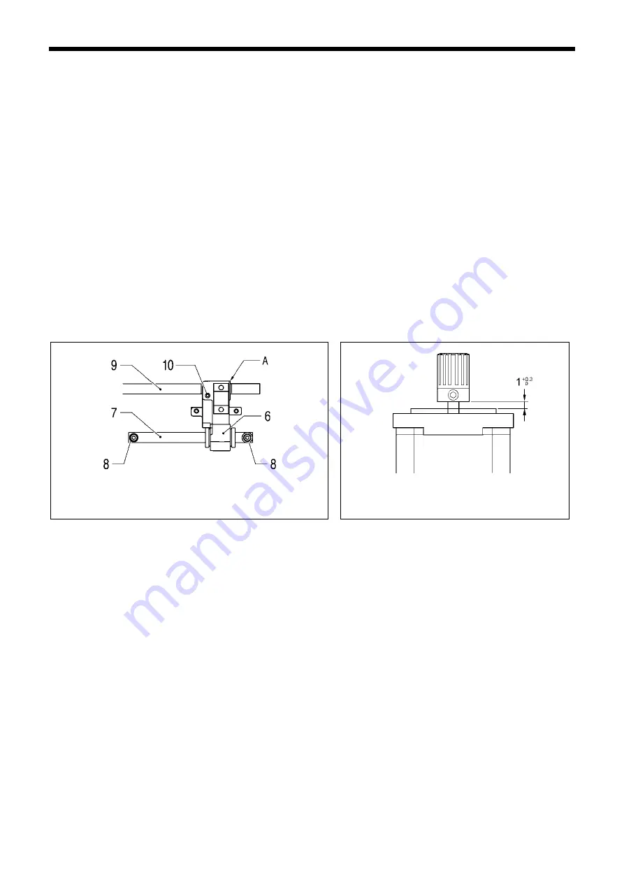
6. Feed arm support base
7. Feed guide shaft A
8. Socket bolts [2 pcs]
(Temporarily tighten)
9. Feed guide shaft B
10. Set screw
11. Socket bolts [2 pcs] (Fully
tighten)
12. Ball bearing [2 pcs]
13. Timing belt
14. Pulley
15. Support shaft
16. Set screws [2 pcs]
17. Belt holder
18. Bolt [2 pcs]
19. Pulley
20. Set screws [2 pcs]
21. Feed motor
22. Motor mounting bracket
23. Socket bolts [4 pcs]
24. Plain washers [3 pcs]
25. Screws [3 pcs]
26. Socket bolt
27. Nut
28. Feed sensor
29. Screw
30. Feed sensor support plate
31. Washers [2 pcs]
32. Screws [2 pcs]
33. Length feed plate
34. Spring washers [2 pcs]
35. Socket bolts [2 pcs]
(Temporarily tighten)
36. Feed presser plate [2 pcs]
37. Screws [4 pcs]
38. Socket bolts [2 pcs] (Fully
tighten)
39. Feed cover
40. Plain washer
41. Socket bolt
42. Cam
43. Washers [2 pcs]
44. Socket bolts [2 pcs]
45. Support plate
46. Washers [2 pcs]
47. Socket bolts [2 pcs]
48. Feed arm
49. Feed arm support shaft
50. Set screw
51. Spring
52. Work clamp assembly
53. Shoulder screw
54. Feed arm support
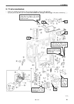
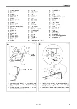
a. Work clamp support M
b. Work clamp 25RS
c. Spring plate [2 pcs]
d. Screws [2 pcs]
e. Finger guard M
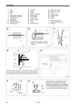
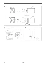
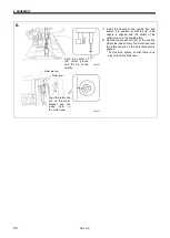
A
Align reference line A on feed guide shaft B with the edge of the
feed arm support base, and then tighten the set screw (10).
B
Assemble as shown in the illustration.
0673D
0772D
Summary of Contents for HE-800B
Page 7: ...v HE 800B Oil tank accessory 4732M 4731M 4730M ...
Page 75: ...6 ASSEMBLY HE 800B 66 D E 0688D 0690D ...
Page 126: ...9 ELECTRIC MECHANISM HE 800B 117 Power PCB Cutter PCB LCD panel PCB 0831D 0768D 0769D ...
Page 133: ...9 ELECTRIC MECHANISM HE 800B 124 0851D ...
Page 134: ...9 ELECTRIC MECHANISM HE 800B 125 0852D ...
Page 135: ...9 ELECTRIC MECHANISM HE 800B 126 0853D ...
Page 177: ...MEMO 168 HE 800B ...
Page 178: ...SERVICE MANUAL 2014 Brother Industries Ltd All Rights Reserved HE 800B I3061003D 2014 03 D 1 ...

