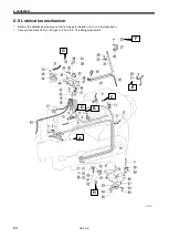
6. ASSEMBLY
HE-800B
71
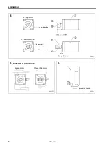
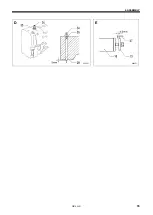
C
1
)
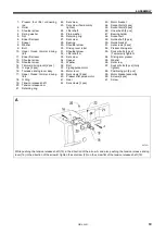
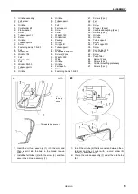
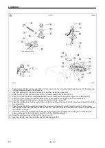
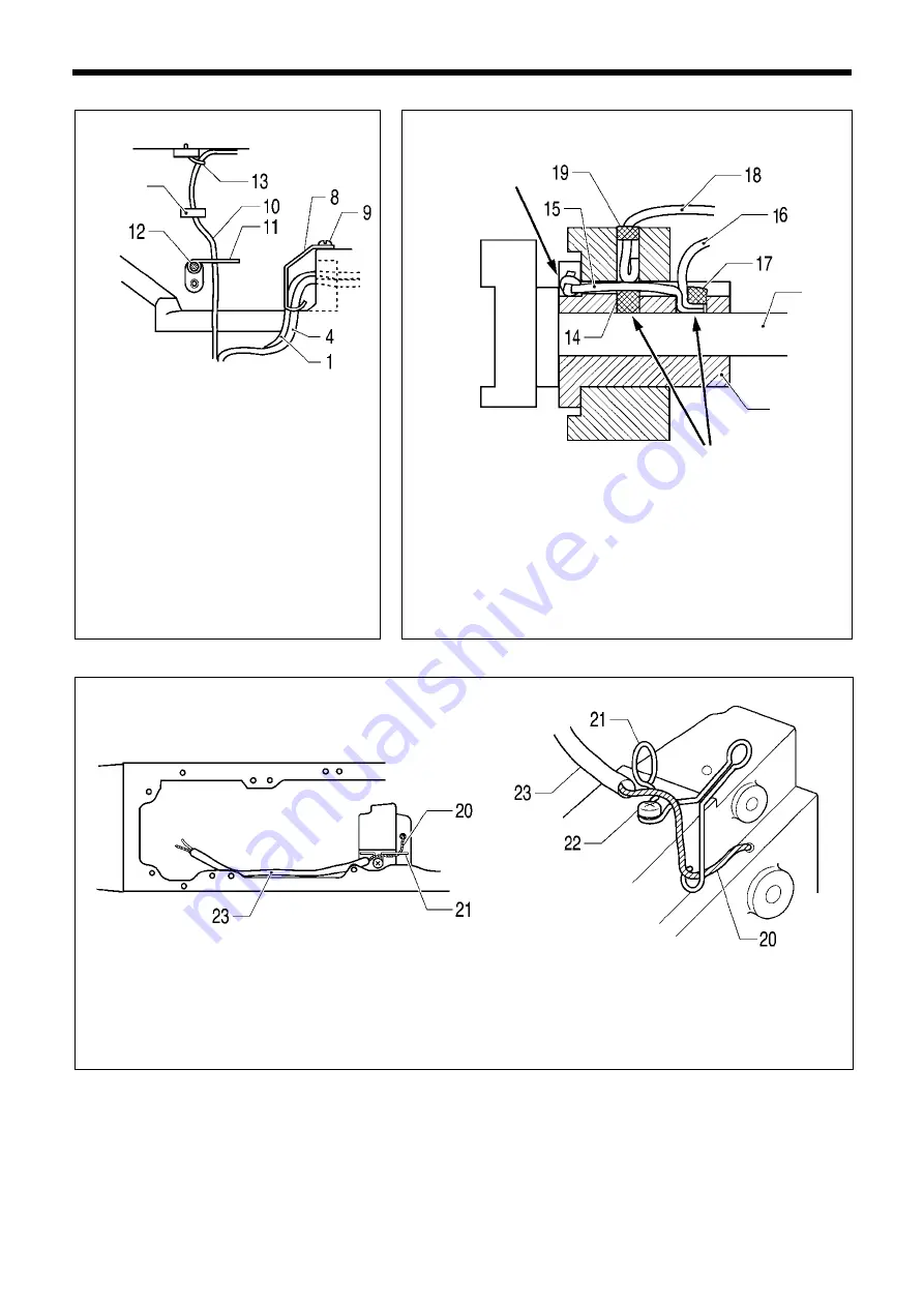
Install the tube support (8) with the screw
(9), and then secure the oil assembly (1)
and the oil tube (4) that is connected
between the oil terminal and the oil outlet
so that they do not touch the pulse motor
(for presser lifter).
2
)
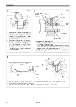
Install the oil tube (10) that is connected to
the oil terminal and the plunger pump with
the tube support M (11) and the screw
(12), pass it through the arm hole, and
then secure it to the arm with the fastening
band (13).
* At this time, bind the oil tube carefully so
as not to break it.
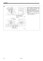
D
1
)
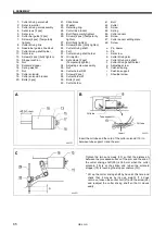
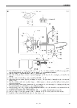
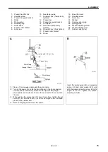
Insert the felt (14) into the bush F.
2
)
Insert the wicks (15) and (16) into the bush F, and insert the felt
(17) to stop them from coming out.
* At this time, push in firmly so that the felt (14) and the wick (15)
are touching the upper shaft. If they are not pushed in firmly
enough, seizure of the upper shaft may occur.
3
)
Insert the wick (18) into the bush F, and insert the felt (19) to stop
them from coming out.
E
1
)
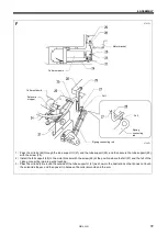
Pass the wick (20) through the tube support U (21) and push it firmly into the zigzag lever shaft lubrication hole.
2
)
Install the tube support U (21) with the screw (22).
3
)
Pass the oil tube (23) around the outside of the tube support U (21) as shown in the illustration.
0699D
0700D
Wick should not
protrude
from here
Upper
shaft
Bush F
Push so they touch
the upper shaft
0698D
0697D
Arm hole
Summary of Contents for HE-800B
Page 7: ...v HE 800B Oil tank accessory 4732M 4731M 4730M ...
Page 75: ...6 ASSEMBLY HE 800B 66 D E 0688D 0690D ...
Page 126: ...9 ELECTRIC MECHANISM HE 800B 117 Power PCB Cutter PCB LCD panel PCB 0831D 0768D 0769D ...
Page 133: ...9 ELECTRIC MECHANISM HE 800B 124 0851D ...
Page 134: ...9 ELECTRIC MECHANISM HE 800B 125 0852D ...
Page 135: ...9 ELECTRIC MECHANISM HE 800B 126 0853D ...
Page 177: ...MEMO 168 HE 800B ...
Page 178: ...SERVICE MANUAL 2014 Brother Industries Ltd All Rights Reserved HE 800B I3061003D 2014 03 D 1 ...

