


App. 1-27
Confidential
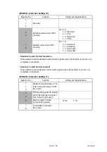
<WSW23> (Communications setting)
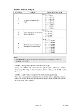
• Selector 1: Starting point of training check (TCF)
At the training phase of receiving operation, the called station detects for 1.0 second a
training check (TCF) command, a series of zeros which is sent from the calling station for
1.5 seconds to verify training and give the first indication of the acceptability of the line.
This selector sets the starting point from which the called station should start counting
those zeros. If this selector is set to "0," the called station starts counting zeros 100 ms
after the head of a series of zeros is detected.
If it is set to "1," the called station starts counting zeros upon detection of 10-ms successive
zeros 50 ms after the head of a series of zeros is detected. In this case, if the detection of
10-ms successive zeros is too late, the data counting period will become less than 1.0
second, making the called station judge the line condition unacceptable.
• Selectors 2 and 3: Allowable training error rate
The called station checks a series of zeros gathered in training (as described in Selector 1)
according to the allowable training error rate set by these selectors. If the called station
judges the line condition to be accepted, it responds with CFR; if not, it responds with FTT.
• Selectors 4 and 5: Decoding error rate for transmission of RTN
The machine checks the actual decoding errors and then transmits an RTN according to
the decoding error rate (Number of lines containing an error per page ÷ Total number of
lines per page) set by these selectors.
• Selector 8: Limitation of attenuation level
Setting this selector to "0" limits the transmitting level of the modem to -10 dB. This setting
has priority over the settings selected by WSW02 (selectors 5 through 8) and WSW13
(selectors 5 through 8).
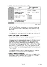
Selector No.
Function
Setting and Specifications
1
Starting point of training check
(TCF)
0: 0 From the head of a series of zeros
1: From any arbitrary point
2
3
Allowable training error rate
No. 2 3
0 0: 0 %
0 1: 0.5 %
1 0: 1 %
1 1: 2 %
4
5
Decoding error rate for
transmission of RTN
No. 4 5
0 0: 16 %
0 1: 14%
1 0: 10 %
1 1: 8 %
6
7
Not used.
8
Limitation of attenuation level
0: Yes
1: No
Note:
• Selector 8 is not applicable to the French/Japan/China models.
Summary of Contents for DCP 8085DN
Page 13: ...CHAPTER 1 SPECIFICATIONS ...
Page 52: ...Confidential CHAPTER 2 THEORY OF OPERATION ...
Page 69: ...2 16 Confidential 3 3 Paper Feeding Fig 2 18 LT path DX path MP path Paper tray path ...
Page 89: ...CHAPTER 3 ERROR INDICATION AND TROUBLESHOOTING ...
Page 178: ...Confidential CHAPTER 4 PERIODICAL MAINTENANCE ...
Page 248: ...CHAPTER 5 DISASSEMBLY REASSEMBLY ...
Page 265: ...5 12 Confidential Fig 5 7 EM2 4 places Separation pad ASSY ...
Page 501: ...Confidential CHAPTER 6 ADJUSTMENTS AND UPDATING OF SETTINGS REQUIRED AFTER PARTS REPLACEMENT ...
Page 507: ...6 5 Confidential 8 Alert warning message of WHQL appears Click Continue Anyway to proceed ...
Page 516: ...CHAPTER 7 SERVICE MODE ...
Page 525: ...7 7 Confidential For color scanning Fig 7 2 ...
Page 527: ...7 9 Confidential For white and black scanning Fig 7 3 ...
Page 528: ...7 10 Confidential For color scanning Fig 7 4 ...
Page 567: ...Confidential CHAPTER 8 CIRCUIT DIAGRAMS WIRING DIAGRAM ...
Page 569: ...8 1 Confidential 1 CIRCUIT DIAGRAMS High voltage Power Supply PCB Circuit Diagram Fig 8 1 ...
Page 570: ...8 2 Confidential LVPS PCB Circuit Diagram 230V Fig 8 2 ...
Page 571: ...8 3 Confidential LVPS PCB Circuit Diagram 115V Fig 8 3 ...


