


5-209
Confidential
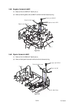
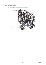
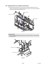
9.39 Toner LED PCB Unit ASSY
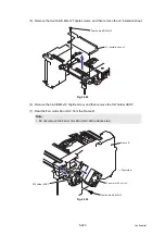
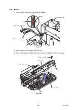
(1) Remove the pan B M3x8 Taptite screw, and remove the Regist ground spring.
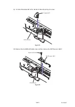
(2) Remove the Toner LED PCB unit ASSY from the Frame R.
Fig. 5-258
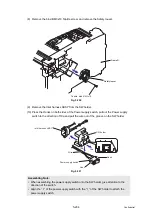
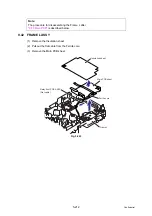
Fig. 5-259
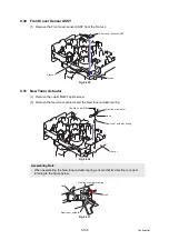
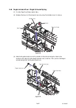
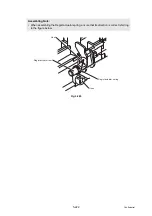
Assembling Note:
• Hang the Hook of the Regist ground spring on the Pinch spring and hang the ring part of
the Regist ground spring on the Pin, and secure the end part and the Toner LED PCB
unit ASSY to the Frame R with the screw.
Regist ground spring
Taptite, pan B M3x8
Toner LED PCB unit ASSY
Hook
Pins
Frame R
<Right side>
Taptite, pan B M3x8
Toner LED PCB unit ASSY
Pinch spring
Hook
Pin
Regist ground spring
Frame R
Summary of Contents for DCP 8085DN
Page 13: ...CHAPTER 1 SPECIFICATIONS ...
Page 52: ...Confidential CHAPTER 2 THEORY OF OPERATION ...
Page 69: ...2 16 Confidential 3 3 Paper Feeding Fig 2 18 LT path DX path MP path Paper tray path ...
Page 89: ...CHAPTER 3 ERROR INDICATION AND TROUBLESHOOTING ...
Page 178: ...Confidential CHAPTER 4 PERIODICAL MAINTENANCE ...
Page 248: ...CHAPTER 5 DISASSEMBLY REASSEMBLY ...
Page 265: ...5 12 Confidential Fig 5 7 EM2 4 places Separation pad ASSY ...
Page 501: ...Confidential CHAPTER 6 ADJUSTMENTS AND UPDATING OF SETTINGS REQUIRED AFTER PARTS REPLACEMENT ...
Page 507: ...6 5 Confidential 8 Alert warning message of WHQL appears Click Continue Anyway to proceed ...
Page 516: ...CHAPTER 7 SERVICE MODE ...
Page 525: ...7 7 Confidential For color scanning Fig 7 2 ...
Page 527: ...7 9 Confidential For white and black scanning Fig 7 3 ...
Page 528: ...7 10 Confidential For color scanning Fig 7 4 ...
Page 567: ...Confidential CHAPTER 8 CIRCUIT DIAGRAMS WIRING DIAGRAM ...
Page 569: ...8 1 Confidential 1 CIRCUIT DIAGRAMS High voltage Power Supply PCB Circuit Diagram Fig 8 1 ...
Page 570: ...8 2 Confidential LVPS PCB Circuit Diagram 230V Fig 8 2 ...
Page 571: ...8 3 Confidential LVPS PCB Circuit Diagram 115V Fig 8 3 ...


