


5-243
Confidential
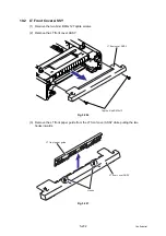
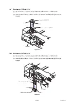
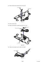
10.11 LT Solenoid ASSY
(1) Remove the bind B M3x10 Taptite screw, and then remove the LT solenoid ASSY.
(2) Remove the Solenoid release spring P/R from the LT solenoid ASSY.
Fig. 5-315
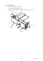
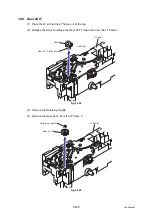
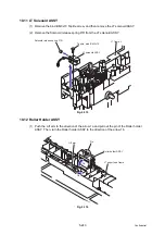
10.12 Roller Holder ASSY
(1) Push the Lift arm to the direction of the arrow 1a and pull out the pin of the Roller holder
ASSY. Then, turn the Roller holder ASSY to the direction of the arrow 1b.
Fig. 5-316
Solenoid release spring P/R
Taptite, bind B M3x10
LT solenoid ASSY
LT frame L
Lift arm
Pin
Roller holder ASSY
LT paper feed frame
1b
1a
Summary of Contents for DCP 8085DN
Page 13: ...CHAPTER 1 SPECIFICATIONS ...
Page 52: ...Confidential CHAPTER 2 THEORY OF OPERATION ...
Page 69: ...2 16 Confidential 3 3 Paper Feeding Fig 2 18 LT path DX path MP path Paper tray path ...
Page 89: ...CHAPTER 3 ERROR INDICATION AND TROUBLESHOOTING ...
Page 178: ...Confidential CHAPTER 4 PERIODICAL MAINTENANCE ...
Page 248: ...CHAPTER 5 DISASSEMBLY REASSEMBLY ...
Page 265: ...5 12 Confidential Fig 5 7 EM2 4 places Separation pad ASSY ...
Page 501: ...Confidential CHAPTER 6 ADJUSTMENTS AND UPDATING OF SETTINGS REQUIRED AFTER PARTS REPLACEMENT ...
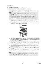
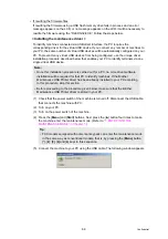
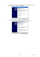
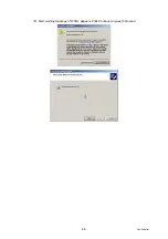
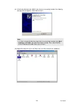
Page 507: ...6 5 Confidential 8 Alert warning message of WHQL appears Click Continue Anyway to proceed ...
Page 516: ...CHAPTER 7 SERVICE MODE ...
Page 525: ...7 7 Confidential For color scanning Fig 7 2 ...
Page 527: ...7 9 Confidential For white and black scanning Fig 7 3 ...
Page 528: ...7 10 Confidential For color scanning Fig 7 4 ...
Page 567: ...Confidential CHAPTER 8 CIRCUIT DIAGRAMS WIRING DIAGRAM ...
Page 569: ...8 1 Confidential 1 CIRCUIT DIAGRAMS High voltage Power Supply PCB Circuit Diagram Fig 8 1 ...
Page 570: ...8 2 Confidential LVPS PCB Circuit Diagram 230V Fig 8 2 ...
Page 571: ...8 3 Confidential LVPS PCB Circuit Diagram 115V Fig 8 3 ...


