


1-32
Confidential
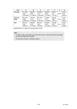
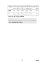
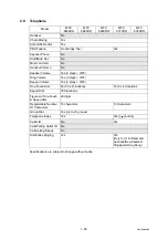
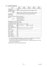
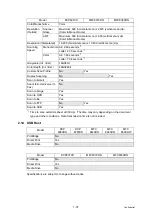
Specifications are subject to change without notice.
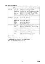
Receiving Easy Receive/
Fax Detect
Yes
Polling
Receiving
Yes
Auto
Reduction
Yes
Duplex Fax
Receive
Yes
Out-of-Paper
Reception
(ITU-T Chart)
Up to 500 pages (ITU-T Test Chart, Standard Resolution, JBIG)
Up to 600 pages (Brother #1Chart, Standard Resolution, JBIG)
Fax Rx Stamp Yes
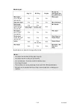
Memory Transmission
(ITU-T Chart)
Up to 500 pages (ITU-T Test Chart#1, Standard Resolution, JBIG)
Up to 600 pages (Brother #1Chart, Standard Resolution, JBIG)
ECM
(Error Correction Mode)
Yes
Error Re-Transmission
Yes
Broadcasting
Yes (390 locations)
Yes (366 locations)
Manual Broadcasting
Yes (50 locations )
Fax Forwarding
Yes
Fax Forwarding Broadcast Yes
Duplex Fax Send
No
Yes
No
Yes
Dial Restriction
Yes
Model
MFC
8480DN
MFC
8880DN
MFC
8890DW
MFC
8370DN
MFC
8380DN
Summary of Contents for DCP 8085DN
Page 13: ...CHAPTER 1 SPECIFICATIONS ...
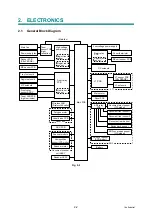
Page 52: ...Confidential CHAPTER 2 THEORY OF OPERATION ...
Page 69: ...2 16 Confidential 3 3 Paper Feeding Fig 2 18 LT path DX path MP path Paper tray path ...
Page 89: ...CHAPTER 3 ERROR INDICATION AND TROUBLESHOOTING ...
Page 178: ...Confidential CHAPTER 4 PERIODICAL MAINTENANCE ...
Page 248: ...CHAPTER 5 DISASSEMBLY REASSEMBLY ...
Page 265: ...5 12 Confidential Fig 5 7 EM2 4 places Separation pad ASSY ...
Page 501: ...Confidential CHAPTER 6 ADJUSTMENTS AND UPDATING OF SETTINGS REQUIRED AFTER PARTS REPLACEMENT ...
Page 507: ...6 5 Confidential 8 Alert warning message of WHQL appears Click Continue Anyway to proceed ...
Page 516: ...CHAPTER 7 SERVICE MODE ...
Page 525: ...7 7 Confidential For color scanning Fig 7 2 ...
Page 527: ...7 9 Confidential For white and black scanning Fig 7 3 ...
Page 528: ...7 10 Confidential For color scanning Fig 7 4 ...
Page 567: ...Confidential CHAPTER 8 CIRCUIT DIAGRAMS WIRING DIAGRAM ...
Page 569: ...8 1 Confidential 1 CIRCUIT DIAGRAMS High voltage Power Supply PCB Circuit Diagram Fig 8 1 ...
Page 570: ...8 2 Confidential LVPS PCB Circuit Diagram 230V Fig 8 2 ...
Page 571: ...8 3 Confidential LVPS PCB Circuit Diagram 115V Fig 8 3 ...


