


3-75
Confidential
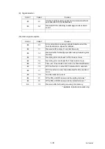
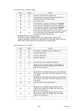
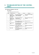
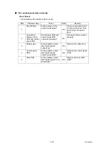
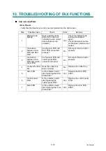
■
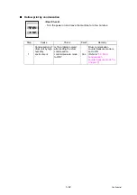
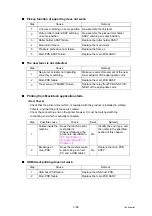
No bell ring.
Step
Possible cause
Check
Result
Remedy
1
Ring delay
Ring delay is set to “0”.
Yes
Change the ring delay
settings to another value.
2
Ring volume
Ring volume is set to
“OFF”.
Yes
Change the ring volume
setting to another value.
3
Connection
between main
PCB and NCU
PCB
Are the main PCB and
NCU PCB connected
properly?
No
Reconnect the connector
properly.
4
Speaker
Is the problem solved
after replacing the
speaker?
Yes
Replace the Speaker.
5
NCU PCB
Is the problem solved
after replacing the NCU
PCB ASSY?
Yes
Replace the NCU PCB
ASSY.
6
Main PCB
Is the problem solved
after replacing the main
PCB ASSY?
Yes
Replace the main PCB
ASSY.
Summary of Contents for DCP 8085DN
Page 13: ...CHAPTER 1 SPECIFICATIONS ...
Page 52: ...Confidential CHAPTER 2 THEORY OF OPERATION ...
Page 69: ...2 16 Confidential 3 3 Paper Feeding Fig 2 18 LT path DX path MP path Paper tray path ...
Page 89: ...CHAPTER 3 ERROR INDICATION AND TROUBLESHOOTING ...
Page 178: ...Confidential CHAPTER 4 PERIODICAL MAINTENANCE ...
Page 248: ...CHAPTER 5 DISASSEMBLY REASSEMBLY ...
Page 265: ...5 12 Confidential Fig 5 7 EM2 4 places Separation pad ASSY ...
Page 501: ...Confidential CHAPTER 6 ADJUSTMENTS AND UPDATING OF SETTINGS REQUIRED AFTER PARTS REPLACEMENT ...
Page 507: ...6 5 Confidential 8 Alert warning message of WHQL appears Click Continue Anyway to proceed ...
Page 516: ...CHAPTER 7 SERVICE MODE ...
Page 525: ...7 7 Confidential For color scanning Fig 7 2 ...
Page 527: ...7 9 Confidential For white and black scanning Fig 7 3 ...
Page 528: ...7 10 Confidential For color scanning Fig 7 4 ...
Page 567: ...Confidential CHAPTER 8 CIRCUIT DIAGRAMS WIRING DIAGRAM ...
Page 569: ...8 1 Confidential 1 CIRCUIT DIAGRAMS High voltage Power Supply PCB Circuit Diagram Fig 8 1 ...
Page 570: ...8 2 Confidential LVPS PCB Circuit Diagram 230V Fig 8 2 ...
Page 571: ...8 3 Confidential LVPS PCB Circuit Diagram 115V Fig 8 3 ...


