


3-65
Confidential
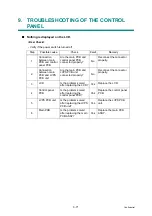
8. TROUBLESHOOTING OF THE
COMMUNICATIONS ERRORS
If a communications error occurs, the facsimile equipment
(1) Gives the alarm (intermittent bleep) for approximately four seconds.
(2) Indicates the appropriate error message on the LCD.
(3) Prints the transmission report during fax transmission.
■
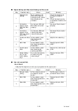
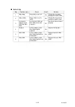
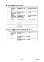
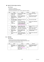
Definition of error codes on the communications list
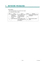
(1)
Calling
Code 1
Code 2
Causes
10
08
Wrong number called.
11
01
No dial tone detected before start of dialing.
11
02
Busy tone detected before dialing.
11
03
2nd dial tone not detected.
11
05
No loop current detected. *
11
06
Busy tone detected after dialing or called.
11
07
No response from the remote station in sending.
11
10
Unobtainable tone detected after dialing.
17
07
No response from the calling station in receiving.
* Available in German models only.
Summary of Contents for DCP 8085DN
Page 13: ...CHAPTER 1 SPECIFICATIONS ...
Page 52: ...Confidential CHAPTER 2 THEORY OF OPERATION ...
Page 69: ...2 16 Confidential 3 3 Paper Feeding Fig 2 18 LT path DX path MP path Paper tray path ...
Page 89: ...CHAPTER 3 ERROR INDICATION AND TROUBLESHOOTING ...
Page 178: ...Confidential CHAPTER 4 PERIODICAL MAINTENANCE ...
Page 248: ...CHAPTER 5 DISASSEMBLY REASSEMBLY ...
Page 265: ...5 12 Confidential Fig 5 7 EM2 4 places Separation pad ASSY ...
Page 501: ...Confidential CHAPTER 6 ADJUSTMENTS AND UPDATING OF SETTINGS REQUIRED AFTER PARTS REPLACEMENT ...
Page 507: ...6 5 Confidential 8 Alert warning message of WHQL appears Click Continue Anyway to proceed ...
Page 516: ...CHAPTER 7 SERVICE MODE ...
Page 525: ...7 7 Confidential For color scanning Fig 7 2 ...
Page 527: ...7 9 Confidential For white and black scanning Fig 7 3 ...
Page 528: ...7 10 Confidential For color scanning Fig 7 4 ...
Page 567: ...Confidential CHAPTER 8 CIRCUIT DIAGRAMS WIRING DIAGRAM ...
Page 569: ...8 1 Confidential 1 CIRCUIT DIAGRAMS High voltage Power Supply PCB Circuit Diagram Fig 8 1 ...
Page 570: ...8 2 Confidential LVPS PCB Circuit Diagram 230V Fig 8 2 ...
Page 571: ...8 3 Confidential LVPS PCB Circuit Diagram 115V Fig 8 3 ...


