


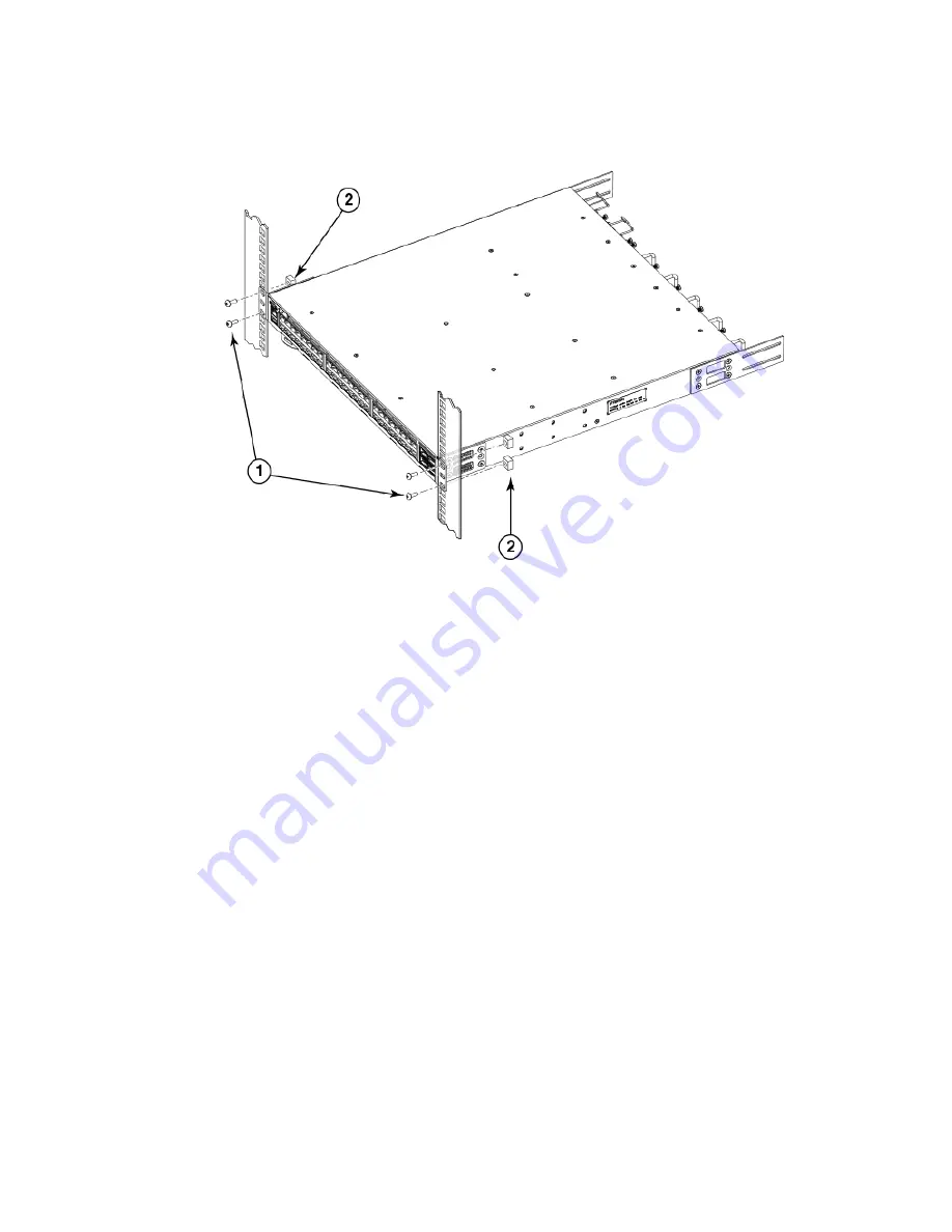
FIGURE 30 Positioning the device in the rack
1.
Screws, 10-32 x 5/8-in., panhead Phillips
2.
Retainer nuts, 10-32
Attaching the rear brackets to the extensions
Complete the following steps to attach the rear brackets to the extensions. There are short and long rear brackets that you can use for
this step. Choose the correct bracket for the depth of your rack.
1.
Select the proper length rear bracket for your rack depth.
2. Slide the right rear bracket onto the right extension and attach to the extension by inserting four 6-32 x 1/4-in. panhead screws
through the bracket holes. If possible, leave at least one empty vertical pair of holes between the screws for better support.
3. Repeat step 2 to attach the left rear bracket to the left extension.
4. Adjust the brackets to the rack depth and tighten all the 6-32 x 1/4-in. screws to a torque of 9 in-lb (10 cm-kg).
Installation
Brocade ICX 7250 Switch Hardware Installation Guide
53-1003898-02
49
Summary of Contents for ICX 7250
Page 10: ...Preface Brocade ICX 7250 Switch Hardware Installation Guide 10 53 1003898 02 ...
Page 12: ...About This Document Brocade ICX 7250 Switch Hardware Installation Guide 12 53 1003898 02 ...
Page 22: ...Overview Brocade ICX 7250 Switch Hardware Installation Guide 22 53 1003898 02 ...
Page 80: ...Installing the EPS4000 Brocade ICX 7250 Switch Hardware Installation Guide 80 53 1003898 02 ...
Page 92: ...Configuring the Device Brocade ICX 7250 Switch Hardware Installation Guide 92 53 1003898 02 ...
Page 114: ...Regulatory Statements Brocade ICX 7250 Switch Hardware Installation Guide 114 53 1003898 02 ...


