High-speed Positioning System
Connecting the Peripherals | en
27
Bosch Security Systems, Inc.
Installation Manual
F.01U.164.491 | 2.0 | 2010.03
5.2
Connecting to the IR360 Base
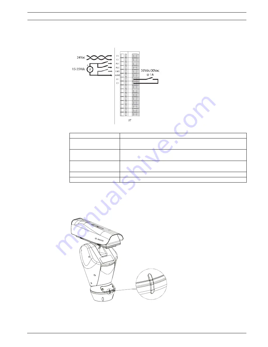
The IR360 base has a 16-pin connector for which the following connections are illustrated:
5.3
Fixing the Top Unit
Each time the top unit requires re-assembling, the screw seals should be replaced (use a
calibrated torque wrench setting of 2.1 Nm) to ensure the appliance remains water tight.
To attach the top of the unit to the base, do the following:
Figure 5.2
Aligning the Tabs
Reference
Description
F1 and F2
Feed 1, 24 VAC for optional washer; Feed 2, 24 VAC for optional
washer
O1 and C1
(O=Output, C=Common)
Dry contact output that can be activated by alarm or by user (50
VDC or 30 VAC @ 1A)
AL1 and AL2
Alarm inputs 1-2, voltage-controlled (10-35 VDC supplied
externally), referred to AGND
AGND
Alarm Ground & External IR probe common
LNO
External photosensor/IR probe


