11.3.6
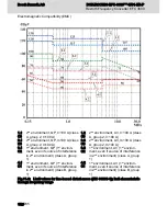
Design and installation in area C – strongly interference-suscep‐
tible area of control cabinet
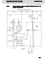
Area C mainly concerns the motor power cables, especially at the connection point at
the drive controller.
Influence of the Motor Power Cable
The longer the motor cable, the greater its leakage capacitors. To comply with a certain
EMC limit value, the allowed leakage capacitance of he mains filter is limited.
● Run the shortest possible motor power cables.
Routing the Motor Power Cables and Motor Encoder Cables
Route the motor power cables and motor encoder cables along grounded metal surfa‐
ces, both inside the control cabinet and outside of it, in order to minimize radiation of
interference fields. If possible, route the motor power cables and motor encoder cables
in metal-grounded cable ducts.
Route the motor power cables and motor encoder cables
● with a distance of at least d5=100 mm to inference-free lines, as well as to signal
cables and signal lines
(alternatively separated by a grounded distance plate)
● in separate cable ducts, if possible
Routing the Motor Power Cables and Mains Connection Lines
For frequency converters (drive controllers with individual mains connection), route mo‐
tor power cables and (unfiltered) mains connection lines in parallel for a maximum dis‐
tance of 300 mm. After that distance, route motor power cables and power supply ca‐
bles in opposite directions and preferably in separate cable ducts.
Ideally, the outlet of the motor power cables at the control cabinet should be provided in
a distance of at least d3=200 mm from the (filtered) power supply cable.
11.3.7
Ground connections
Housing and Mounting Plate
By means of appropriate ground connections, it is possible to avoid the emission of in‐
terference, because interference is discharged to ground on the shortest possible way.
Ground connections of the metal housings of EMC-critical components (such as filters,
devices of the frequency converter, connection points of the cable shields, devices with
microprocessor and switching power supply units) have to be well contacted over a
large surface area. This also applies to all screw connections between mounting plate
and control cabinet wall and to the mounting of a ground bus to the mounting plate. The
best solution is to use a zinc-coated mounting plate. Compared to a lacquered plate,
the connections in this area have a good long-time stability.
DOK-RCON03-EFC-3600***-IT01-EN-P
Rexroth Frequency Converter EFC 3600
Bosch Rexroth AG
Electromagnetic Compatibility (EMC)
163/235
Summary of Contents for Rexroth EFC 3600
Page 6: ...Bosch Rexroth AG DOK RCON03 EFC 3600 IT01 EN P Rexroth Frequency Converter EFC 3600 IV 235 ...
Page 232: ...230 235 ...
Page 236: ...Bosch Rexroth AG DOK RCON03 EFC 3600 IT01 EN P Rexroth Frequency Converter EFC 3600 234 235 ...
Page 237: ...Notes DOK RCON03 EFC 3600 IT01 EN P Rexroth Frequency Converter EFC 3600 Bosch Rexroth AG ...


