


Reviews:
No comments
Related manuals for JOHB-SMP3-MA

VLT DriveMotor FCP 106
Brand: Danfoss Pages: 82

VLT AQUA Drive FC 202
Brand: Danfoss Pages: 88

VLT AutomationDrive FC 301
Brand: Danfoss Pages: 92

VLT AutomationDrive FC 301
Brand: Danfoss Pages: 16

PW-SE
Brand: Yamaha Pages: 13

4PS-2
Brand: Plextor Pages: 26

DS5B Series
Brand: Xinje Pages: 109

SF8300
Brand: MAIMAN ELECTRONICS Pages: 27

LaserMemory DVD-305S
Brand: Pioneer Pages: 8

LaserMemory DVD-303S
Brand: Pioneer Pages: 8

LaserMemory DVD-117
Brand: Pioneer Pages: 8

DVR-212
Brand: Pioneer Pages: 2

DVR-2920Q - DVD±RW / DVD-RAM Drive
Brand: Pioneer Pages: 2

DVR-220LBK
Brand: Pioneer Pages: 2

DVR-116D
Brand: Pioneer Pages: 2

DVR-115D Series
Brand: Pioneer Pages: 2

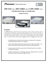
DVR-112D - DVD±RW Drive - IDE
Brand: Pioneer Pages: 3
DVR-112D
Brand: Pioneer Pages: 2


