


8.10
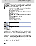
Group E4: Error and Protection
E4.01
Overvoltage prevention setting
Setting range
0 ~ 2
Minimum unit
1
Factory default 0
● 0: Both disabled
● 1: Stall protection enabled, braking disabled
● 2: Stall protection disabled, braking enabled
When [E4.01]=0 / 1, the brake chopper will not work even its action point is reached.
When [E4.01]=2, the brake chopper is enabled with the set braking ratio if its action
point is reached, no matter the frequency converter is in stop or running mode.
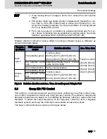
Two factors decide the switching pattern: Maximum duty cycle (duty ratio) and hystere‐
sis voltage.
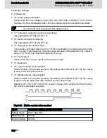
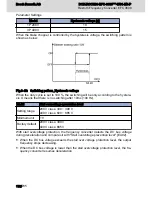
Maximum duty cycle
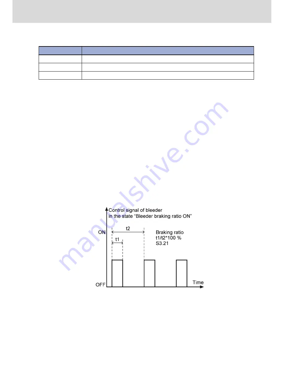
The switching time of the brake chopper is limited with parameter [S3.21]. If the value is
set too low, over voltage errors may happen during braking.
● The time t2=1 / 100 Hz=10ms
● The time t1=t2 x [S3.21] / 100 %
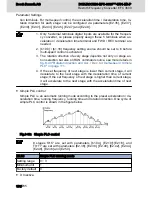
If the switching of the brake chopper is controlled by the maximum duty cycle, the
switching pattern is shown as below:
Fig.8-41: Switching pattern_Maximum duty cycle
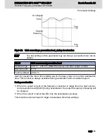
Hysteresis Voltage
The hysteresis voltage of braking is fixed as below:
DOK-RCON03-EFC-3600***-IT01-EN-P
Rexroth Frequency Converter EFC 3600
Bosch Rexroth AG
Parameter Settings
115/235
Summary of Contents for Rexroth EFC 3600
Page 6: ...Bosch Rexroth AG DOK RCON03 EFC 3600 IT01 EN P Rexroth Frequency Converter EFC 3600 IV 235 ...
Page 232: ...230 235 ...
Page 236: ...Bosch Rexroth AG DOK RCON03 EFC 3600 IT01 EN P Rexroth Frequency Converter EFC 3600 234 235 ...
Page 237: ...Notes DOK RCON03 EFC 3600 IT01 EN P Rexroth Frequency Converter EFC 3600 Bosch Rexroth AG ...