15
AQT8 Series
User Manual
Section 5 – RF Input
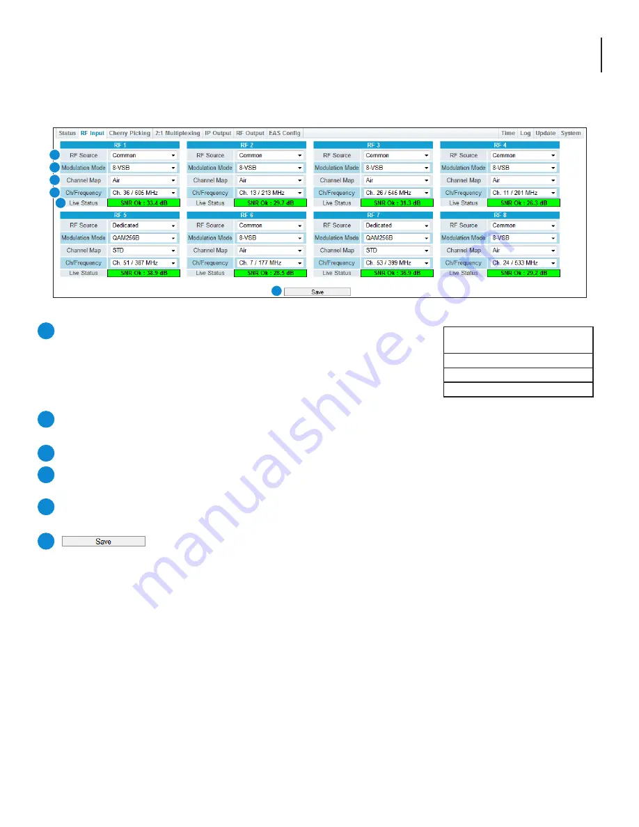
The “RF Input” tab (Figure 5a) is “user-configurable” with the following parameters and status information:
RF Source:
Indicates the physical port of the 8 RF inputs.
Dedicated:
The input is connected to one of 8 dedicated RF ports located
on the rear panel of the unit. Each of these ports are labeled from 1 to 8.
Common: The input is connected to a single RF port labeled “Common” located
on the rear panel of the unit. It is then split internally into 8 identical inputs.
Modulation Mode: Select the appropriate modulation mode to match the
input. See chart (Fig 5b) for a list of supported Modulation modes.
Channel Map: Select the appropriate Channel Map. Options available are: STD, HRC, IRC, and Air.
Ch/Frequency: The input channel and frequency as related to the Modulation Mode and Channel Map. From the pull-
down menu, select the desired channel/frequency (center) for each input.
Live Status: Displays the SNR and the live status of the input signal. Status will be indicated as shown in Figures 4.3b
and 4.3c on page 13.
Press to save changed configurations.
1
2
3
4
5
6
RF Input
Modulation Modes
8VSB
QAM256B
QAM64B
Figure 5b - Modulation Modes
Figure 5a - “RF Input” Tab
1
2
3
4
5
6


