


Section F. Adjustments
Belarus-510/512
Operating manual
72
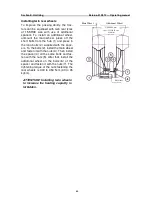
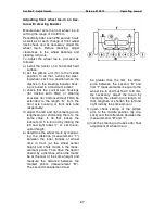
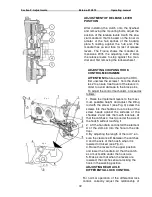
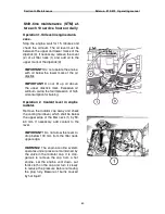
ADJUSTMENT OF RELEASE LEVER
POSITION
After installing the clutch onto the flywheel
and removing the mounting bolts, adjust the
position of the release levers 3 with the spe-
cial mandrel 4 that is based on the inner di-
ameter of the hub splines of the backing
plate 5 resting against the hub end. The
mandrel has an end face for rest of release
levers. The Figure shows the mandrel di-
mensions. With the adjusting nuts 2 bring
the release levers to stop against the man-
drel end, first removing the lock washers 1.
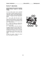
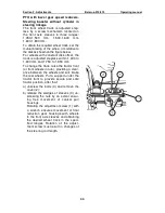
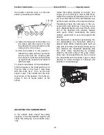
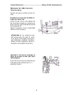
ADJUSTING COUPLING HOOK
CONTROL MECHANISM
ATTENTION!
Before adjusting the HDC,
first unscrew the screws 1 from the shack-
les 2 to ensure free travel of the levers in
order to avoid damage to the brace pins.
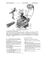
To adjust the control mechanism, proceed as
follows:
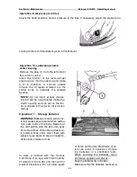
1. Raise the implement levers to the maxi-
mum possible height and adjust the lifting
rod with the screw 1 (see Fig. 3) screw the
screws into the shackles 3 up to stop of the
screw heads against the surfaces of the
shackles 2 and lock them with locknuts. At
that the catches 4 must go under the axis of
the hook 5 without touching it.
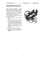
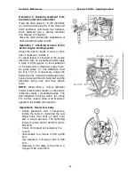
2. Lift the handle 6 and install the element
A of the clamp 6 into the hole in the cab
floor.
3. By adjusting the length of the rod 7, en-
sure the clearance B between the catches
4 and the axis of the hook 5 when it is
lowered or raised (see Fig. 4).
4. Raise the levers to the upper position
and lower the handle 6. At that the catch-
es 4 must settle under the hook axis.
5. Make sure that when the levers are
lowered, the catches ensure locking the
hook in the working position.
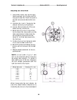
ADJUSTING REAR AXLE
DIFFERENTIAL LOCK CONTROL
For normal operation of the differential lock
control, correctly adjust the relationship of
Fig. 3
Fig. 4


