


Section B. Specifications
Belarus-510/512 Operating manual
24
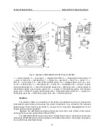
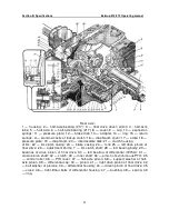
At the rear part of the shaft (24) (Fig. 2), fixed on its splines, the driven pinion of hill-
climbing gears and reverse gears (22) installed, which is constantly meshed with the
smaller gear ring of the pinion (23) (Fig. 1) of the intermediate shaft (29).
On the right side of the GB of the tractors with FDA drive, the axle (27) is installed in
the GB housing borings, on which on two tapered roller bearings the FDA drive pinion (28)
is freely rotating. Power is taken off at the FDA from the driven pinion of Ist stage of the
range reducer (6) (Fig. 1), with which the pinion (28) (Fig. 2) is constantly meshed.
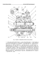
On the front wall of the GB housing (27) (Fig. 1), concentrically to the intermediate
shaft (29), the seat (28) is installed, inside of which the inner shaft front bearing (17) is lo-
cated.
On the right and left sides of the GB housing, there are windows (Fig. 2). The left
window is closed with the cover (17), in which there is a dipstick (18) to control the oil lev-
el. The tractors without an FDA drive have the right window closed with the cover (14), and
the tractors with the FDA drive have the cover (14) removed and the window closed by the
FDA drive transfer box housing (see section).
To drain oil when changing it, a hole is provided in the bottom of the GB housing,
closed with the plug (16).
1.1.2 GB control
The GB control consists of the forks housing (3) (Fig. 1) and the GB control cover
(11) that are installed on the upper plane of the GB housing (27) and bolted to it.
The forks housing (3) (Fig. 1 consists of the fork of 1st gear and reverse gears (19)
(fig. 2), the fork of 3rd and 6th gears (20), the fork of 4th and 5th gears (12) and the range
reducer rod (13), the rails of which are installed in the groove of the housing (1) and can
move along the groove. On the upper surfaces of the rails, there are transverse holes in
which the spring-loaded balls of the latches (10) are inserted, which provide locking of the
forks rails and reducer rail in the desired positions, as well as prevent spontaneous disen-
gagement of the gears under load.
The rod (13) is connected with the shaft (9) (Fig. 1), on which the fork (8) is fixed
that moves the drive pinion of Ist stage of the range reducer (22).
The forks and range reducer rails are separated by three lock strips (11) (Fig. 2).
The strips (11) are installed in the housing (1) fixed and exclude simultaneous movement
of several rails by the gear shifter lever (7) (Fig. 1). When a gear is engaged, the lock
strips (11) lock the gear shifter lever (7) (Fig. 1) in the rail groove of the fork of the gear
engaged.
The GB control cover (11) consists of the cover (21) (Fig. 2), on the upper surface
of which the spherical bearing (6) of the gear shifter lever (7) (Fig. 1) is bolted. When
swinging, the gear shifter lever (7) directly affects the rails in the forks housing (3), causing
their displacement and, consequently, engagement or disengagement of the selected gear
or range in the GB.
To avoid excessive swinging of the gear shifter lever (7), as well as to clearly direct
its motion, the restrictive plate serves (12), which is bolted to the cover (11).
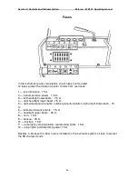
The GB design provides an engine start lock when a gear is engaged in the GB. On
the right side of the cover (21) (Fig. 2), the housing is installed (2) bolted to it. In the hous-
ing (2), the axle (5) of the spring-loaded rocking frame (7) is located. The ring hole of the
frame (7) envelops the gear shifter lever (7) (Fig. 1). At that, rocking of the lever (7) results
in a corresponding movement of the frame (7) (Fig. 2), the axle flat (5) of which affects the
diesel start lock sensor (4) mounted in the threaded hole of the housing (2).
Triggering of the engine start lock is adjusted by the shims (3) located under the


