


Section B. Specifications
Belarus-510/512 Operating manual
26
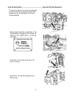
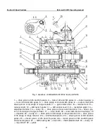
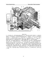
lever (7) (Fig. 1) to the respective positions of those gears (Fig. 3). Further, to engage the
3rd (6th) gear, the operator shifts the GB control lever (7) (Fig. 1) to the position of the said
gears backward (Fig. 3). At that, the gear shifter lever (7), acting on the rail of the fork of
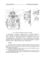
4th and 5th gears, moves the fork (20) (Fig. 2) forward. The sliding pinion of 3rd and 6th
gears (5) controlled by the fork (20) (Fig. 1) engages with the driven pinion of 3rd and 6th
gears (24). By the emerged mesh, power is transferred to the GB intermediate shaft (29).
To engage the 9th (direct) gear, the operator moves the GB control lever (7) (Fig. 1)
from the position of the 3rd (6th) and 9th (direct) forward gears (Fig. 3). At that, the gear
shifter lever (7), acting on the rail of the fork of 3rd and 6th gears, moves the fork (20) (Fig.
2) forward. The sliding pinion of 3rd and 6th gears (5) controlled by the fork (20) (Fig. 1)
engages with the inner gear ring of the output shaft (6), rigidly linking the input (31) and
output (6) shafts.
The 9th (direct) gear must be engaged when the IInd range reducer stage is en-
gaged (Fig. 3).
This will avoid a loud noise in the GB, since the IInd reducer stage has an intermediate
shaft speed (29) (Fig. 1) less than the Ist stage.
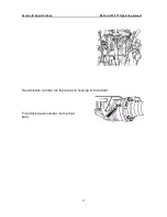
To engage the 4th (7th) or 5th (8th) gear, the operator shifts the GB control lever (7)
(Fig. 1) to the respective positions of those gears (Fig. 3). Further, to engage the 4th or 7th
gear, the operator shifts the GB control lever (7) (Fig. 1) to the position of the said gears
forward. At that, the gear shifter lever (7), acting on the rail of the fork of 4th and 5th gears,
moves the fork (12) (Fig. 2) and the drive pinion unit of 4th and 5th gears (1) controlled by
it (Fig. 1) backward. The smaller gear ring of the unit (1) engages with the driven pinion of
4th and 7th gears (25). By the created mesh, power from the input shaft (31) is transferred
to the GB intermediate shaft (29).
To engage the 5th or 8th gear, the operator shifts the GB control lever (7) (Fig. 1) to
the position of the said gears backward (Fig. 3). At that, the gear shifter lever (7), acting on
the rail of the fork of 4th and 5th gears, moves the fork (12) (Fig. 2) and the drive pinion
unit of 4th and 5th gears (1) controlled by it (Fig. 1) forward. The larger gear ring of the unit
(1) engages with the driven pinion of 5th and 8th gear (26). By the created mesh, power
from the input shaft (31) is transferred to the GB intermediate shaft (29).
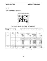
Table 1 shows rated speeds of the BELARUS-510/512 tractor and its modifications
at all GB gears.


