9440300990 Rev J
135
DECS-250
BESTCOMS
Plus
®
Software
1.
Remove the DECS-250 from service. Refer to the appropriate site schematics to ensure that all
steps have been taken to properly and completely de-energize the DECS-250.
2.
Apply only control power to the DECS-250.
3.
Enable the expansion modules that are present in the system. If they have not already been
enabled, enable the expansion modules in the BESTCOMS
Plus
Settings Explorer,
Communications, CAN Bus, Remote Module Setup screen.
4.
Verify that the DECS-250 and the associated expansion modules are communicating. This can
be verified by examining the alarm status using the Metering Explorer in BESTCOMS
Plus
or from
the front panel by navigating to Metering > Status > Alarms. When communications are
functioning properly, there should be no active AEM or CEM Communications Failure alarms.
5.
Connect to the DECS-250 through the USB or Ethernet port if not already connected.
6.
Select Upload Device Files from the Communication pull-down menu.
7.
You will be asked to save the current settings file. Select Yes or No.
8.
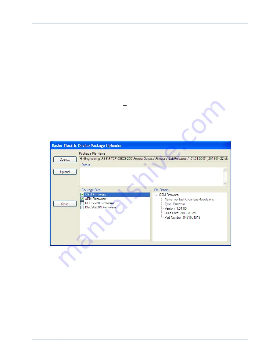
When the Basler Electric Device Package Uploader
screen (Figure 122) appears, click on the
Open button to browse for the device package you have received from Basler Electric. The
Package Files along with File Details are listed. Place a check in the boxes next to the individual
files you want to upload.
Figure 122. Basler Electric Device Package Uploader
9.
Click on the Upload button and the Proceed with Device Upload screen will appear. Select Yes or
No.
10.
After selecting Yes, the DECS-250 Selection screen will appear. Select either USB or Ethernet.
11.
After file(s) have been uploaded, click the
Close
button on the Basler Electric Device Package
Uploader screen and disconnect communication to the DECS-250.
Upgrading Firmware in the DECS-250
The following procedure is used to upgrade firmware in the DECS-250. This must be completed after
upgrading firmware in any expansion modules.
1.
Remove the DECS-250 from service. Refer to the appropriate site schematics to ensure that all
steps have been taken to properly and completely de-energize the DECS-250.
2.
Apply only control power to the DECS-250.
Summary of Contents for DECS-250
Page 2: ......
Page 6: ...iv 9440300990 Rev J Revision History DECS 250 ...
Page 16: ...xiv 9440300990 Rev J Contents DECS 250 ...
Page 20: ...4 9440300990 Rev J Introduction DECS 250 ...
Page 28: ...12 9440300990 Rev J Power Stage DECS 250 ...
Page 32: ...16 9440300990 Rev J Voltage and Current Sensing DECS 250 ...
Page 40: ...24 9440300990 Rev J Synchronizer DECS 250 ...
Page 52: ...36 9440300990 Rev J Auxiliary Control DECS 250 ...
Page 56: ...40 9440300990 Rev J Contact Inputs and Outputs DECS 250 ...
Page 84: ...68 9440300990 Rev J Limiters DECS 250 ...
Page 114: ...98 9440300990 Rev J Power System Stabilizer DECS 250 Figure 96 PSS Parameter Settings ...
Page 124: ...108 9440300990 Rev J Stability Tuning DECS 250 ...
Page 126: ...110 9440300990 Rev J Mounting DECS 250 Figure 103 Overall and Projection Mounting Dimensions ...
Page 127: ...9440300990 Rev J 111 DECS 250 Mounting Figure 104 DECS 250 Escutcheon Plate Dimensions ...
Page 198: ...182 9440300990 Rev J Timekeeping DECS 250 ...
Page 210: ...194 9440300990 Rev J CAN Communication DECS 250 ...
Page 304: ...288 9440300990 Rev J Maintenance DECS 250 ...
Page 316: ...300 9440300990 Rev J Specifications DECS 250 ...
Page 334: ...318 9440300990 Rev J Analog Expansion Module DECS 250 ...
Page 351: ......


